Tag Archives: LinkedIn

DNSSEC secured blog: raising awareness on DNS security

Hurray! My blog and the whole pierky.com domain are now running on a DNSSEC secured zone.

Thanks to the recent moving of the blog from the WordPress.org hosted infrastructure to the OVH hosting service I finally managed to enable IPv6 and DNSSEC support.

If you are using a DNSSEC-aware resolver (are you? check it out…) you can verify it yourself:

:~# dig +dnssec blog.pierky.com

; <<>> DiG 9.8.1-P1 <<>> +multi +dnssec blog.pierky.com
;; global options: +cmd
;; Got answer:
;; ->>HEADER<<- opcode: QUERY, status: NOERROR, id: 31643
;; flags: qr rd ra ad; QUERY: 1, ANSWER: 2, AUTHORITY: 0, ADDITIONAL: 1
...

There it is the ad (Authenticated answer) flag.

If your resolvers are not DNSSEC-aware – what a shame! Tell your ISP to enable them 🙂 – you can try the same using an open resolver which supports DNSSEC, like those of Google…

:~# dig +dnssec blog.pierky.com @8.8.8.8

… or you can try an online test suite, like the one provided by Verisign Labs or DNSViz.

A nice browser addon – available for Internet Explorer, Firefox and Chrome – allows you to check the DNSSEC validity of the domain names in your browser window. It’s name is DNSSEC Validator and it works even if your resolvers are not DNSSEC enabled (you can set an external resolver different from the one in use in your operating system); here it is a screenshot showing my blog’s status:

DNSSEC secured blog as seen by DNSSEC Validator addon

DNSSEC secured blog as seen by DNSSEC Validator addon

(in the above screenshot you can see a green 6 too, originated from another Chrome addon, IPvFoo, which indicates whether the current page was fetched using IPv4 or IPv6).

This is just a small drop in the ocean of Internet, but I like to believe that it might raise awareness about DNS security matter and encourage its adoption (it seems that as of September 2012 only 1.7% of the visible DNS resolvers in the Internet were performing DNSSEC validation).

References

RIPE Labs – Counting and Re-Counting DNSSEC

dnssec-deployment.org – DNSSEC in ccTLDs, Past, Present, and Future/

dnssec-deployment.org – ccTLD DNSSEC Adoption as of 2013-07-30 [PDF]

CZ.NIC – DNSSEC Validator

Verisign Labs – Test if you are benefiting from DNSSEC

Verisign Labs – DNSSEC-Debugger

Sandia.gov – DNSViz

DNS-amplification attack reflection on backhaul circuit

As many of us already know, DNS amplification attacks are a big plague for who fights every day for the sake of Internet security and service availability.

Infected hosts are instructed by botnet controllers to send DNS queries to recursive open resolvers, asking them for big zones with spoofed UDP packets containing the victim’s IP address in the source field, so that a small request would generate a big traffic toward the victim.

Small efforts are needed in order to mitigate those attacks – a proper DNS resolvers configuration to avoid open recursion, IP source validation (such as Cisco uRPF) to block source IP spoofing at the access network layer – but they may not be sufficient to immunize a network against annoying issues.

An unpleasant side effect

Even on secure networks an unpleasant side effect may occur: attack reflection against infected hosts, with the consequent backhaul circuit saturation and users’ downstream degradation.

Take, for example, the following not uncommon scenario:

DNS Amplification Reflection - Scenario

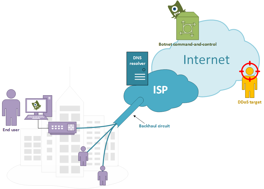
An ISP, running a properly configured DNS resolver, connects many users with a shared backhaul link between its core network and a local metro area; one or more users have infected devices responding to a botnet C&C server who aims to launch a DDoS against a given target.

A well implemented network access layer would stop spoofed packets whose source IP can not be reached through the same link on which they came from. At the same time a properly configured DNS resolver would not let recursive queries to go on by untrusted sources. The problem raises when proper DNS queries came in from trusted users and go to the ISP DNS resolver.

A not-really-failed attack attempt

Failed Attack

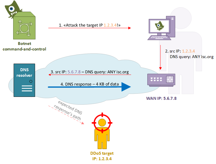
In the above diagram, at step 1, the botnet controller instructs the infected host to start a DNS amplification attack against the victim’s IP address 1.2.3.4. In the step 2 the malicious software tries to send a spoofed packet containing the victim’s address in the source field but something goes wrong: the operating system doesn’t let the malware to forge such a packet and rewrites it using its LAN address, or the router/firewall/CPE changes it with the WAN IP address (NAT). Anyway, at step 3, a proper DNS query comes out the user’s network and heads to the ISP DNS resolver, which in turn sends back a response with the huge DNS zone (step 4).

It’s easy to understand how this behaviour could lead to ISP internal issues regarding the backhaul link saturation and the users experience’s deterioration.

Consequences

A small upstream user’s query (65 bytes for an ANY query on isc.org) produces a big downstream response (~ 4 KB for isc.org zone), with a ~ 60x multiplicative factor. Every infected host may send many and many queries over a long period, even more than 1 query per second for many days, and many compromised hosts may be triggered at the same time by the same botnet controller.

Backhaul links may be rent from incumbent local carriers and may be characterized by an overbooking ratio calculated over the expected usage by customers who share them; high speed links which connect DNS resolvers to the core may overwhelm them when filled by UDP response packets and lead to traffic stagnation because of traffic policing operated by the carrier.

Customers also may report a bad user experience: it’s true, their links are operating at 100% of their capacity, but Facebook is slow and the VoIP is unusable.

A very big headache, even for an ISP with a properly configured network.

Symptoms

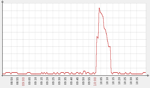
The first symptom that can be observed is an abnormal peak in resolvers bandwidth usage:

DNS resolver bandwidth usage during an attack attempt - response traffic in green

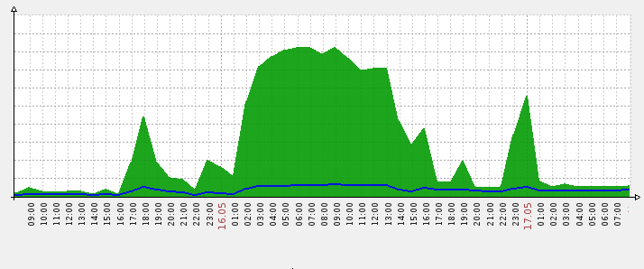
DNS resolver bandwidth usage during an attack attempt – response traffic in green

During an attack attempt the network usage (servers’ upstream) may raise up to hundreds of times higher than average.

NetFlow also may help us to identify this kind of traffic; big response UDP datagrams may be fragmented over the network and they would be shown as port-0 UDP packets in the output of nfdump or similar tools, with an high Bpp (bytes-per-packet) ratio:

Proto Src IP Addr:Port  Dst IP Addr:Port   Packets    Bytes  pps     bps   Bpp Flows
UDP    RESOLVER_1:0   ->  A.B.1.155:0        78966  106.6 M   48  519300  1350    79
UDP    RESOLVER_1:0   ->   G.H.4.73:0        35798   48.3 M   25  274100  1350    38
UDP    RESOLVER_1:53  ->  I.J.5.101:14068     7430    9.3 M    4   46712  1249   187
A 65-bytes request generated a 4157 bytes response in 3 segments - calculated at IP level

A 65-bytes request generated a 4157 bytes response in 3 segments – calculated at IP level

Mitigation

Unfortunately, as far as I know, there are still no specific implementations aimed to mitigate those kind of attack.

BIND9 has a generic rate-limit option which prevents a requestor to be told the same answer more than a specific number of times within a one-second interval, but there is no way to apply it only to a subset of responses (like the ones used in DDoS attack, such as ANY to isc.org or ripe.net). DNS RRL (Response Rate Limiting) is focused on authoritative servers, not on recursive ones.

A suitable way would be the use of the iptables recent module on recursive resolvers, but other aspects have to be considered, such as servers load and performances degradation.
A first deep-packet inspection of the incoming DNS requests would filter those DNS queries whose type has been set to ANY, then the recent module would lookup the source IP address on a local list and drop the packet if it violates the predetermined policy. For example, a policy may allow one or two queries with type = ANY every 5 seconds, so that “regular” usage would be allowed while malware initiated traffic would be dropped within few seconds.

Number of different IP addresses on the recent module's queue - peak during an attack attemp

Number of different IP addresses on the recent module’s queue – peak during an attack attemp

References

“Alert (TA13-088A) DNS Amplification Attacks”, US-Cert: http://www.us-cert.gov/ncas/alerts/TA13-088A

“DNS Response Rate Limiting (DNS RRL)”, Paul Vixie, ISC – Vernon Schryver, Rhyolite: http://ss.vix.su/~vixie/isc-tn-2012-1.txt

Graphing near realtime PPPoE/PPPoA link speed using SNMP Traffic Grapher (STG to its friends)

Sometimes it happens to me that, for troubleshooting reasons, I need to graph PPPoE or PPPoA connections speed from the NAS/BRAS side. These links are terminated on Cisco routers, where other hundreds of CPEs are connected; connections are from dialin users and I can’t have static graphs, mostly because I don’t need endusers monitoring on a fulltime basis and it would only be a huge waste of resources.

In this case a little program helps me: STG, SNMPTrafficGrapher.

STG - SNMPTrafficGrapher

STG – SNMPTrafficGrapher

It’s a small Windows utility that uses SNMP to get counters data and put them on a graph, like MRTG does. It’s easy and fast to deploy (run it, set SNMP OID and it’s ready), does not use many resources and can give you graphs updated every second.

Configuration

From the View / Settings menu you just have to set the device’s IP address and SNMP community, and then to select OID and polling frequency.

As said, users have dialin connections which go up and down and there is no way to predict their SNMP interface’s index; to obtain the right OID we can use the show snmp mib ifmib ifindex command.

Initially we get the actual Virtual-Access interface for the user we need to monitor:

Router#sh users | include MyUserName
  Vi1.195      MyUserName	   PPPoATM      -        10.11.12.13

Then we get it’s SNMP index:

Router#show snmp mib ifmib ifindex Virtual-Access 1.195
Interface = Virtual-Access1.195, Ifindex = 257

And finally we can use it to configure STG:

STG setup

Geen OID = 1.3.6.1.2.1.2.2.1.10.257 (ifInOctets.257)
Blue OID = 1.3.6.1.2.1.2.2.1.16.257 (ifOutOctets.257)

Where 257 is the dynamic SNMP ifIndex of our user’s Virtual-Access interface.

References

STG homepage: http://leonidvm.chat.ru/

Zabbix: monitoring HSRP on Cisco devices

On the basis of my previous post Cisco HSRP monitoring using SNMP I decided to extend the Zabbix lightweight dynamic template for SNMP routers by adding a new template, which uses part of the configuration already seen in order to monitor Cisco HSRP status. Here it is: Template_Cisco_HSRPGroup.

What we need is to have a trigger fired when a device changes its HSRP state on the LAN side; with the right configuration it may help to understand when something goes wrong on the WAN side.

As seen on the Cisco HSRP monitoring using SNMP post we need two parameters: SNMP interface ID and HSRP group. We already have the first, because each monitored host has the macro used by the Template_Lightweight_Dynamic_SNMPv2_Router: {$LAN_IF_IDX}. We just have to add a new macro to the host, {$HSRP_GROUP}, where we’ll put the HSRP group number used in the router’s configuration, and use it in the new template’s items:

Description: HSRP Group {$HSRP_GROUP} state
SNMP OID: .1.3.6.1.4.1.9.9.106.1.2.1.1.15.{$LAN_IF_IDX}.{$HSRP_GROUP}
SNMP community: public
Key: cHsrpGrpStandbyState

Description: HSRP Group {$HSRP_GROUP} active IP
SNMP OID: .1.3.6.1.4.1.9.9.106.1.2.1.1.13.{$LAN_IF_IDX}.{$HSRP_GROUP}
SNMP community: public
Key: cHsrpGrpActiveRouter

Description: HSRP Group {$HSRP_GROUP} standby IP
SNMP OID: .1.3.6.1.4.1.9.9.106.1.2.1.1.14.{$LAN_IF_IDX}.{$HSRP_GROUP}
SNMP community: public
Key: cHsrpGrpStandbyRouter

At this point we add 3 more macros to tell Zabbix which values we expect to find for the HSRP group state, active IP and standby IP: {$HSRP_GROUP_EXPECTED_STATE}, {$HSRP_GROUP_EXPECTED_ACTIVE_IP} and {$HSRP_GROUP_EXPECTED_STANDBY_IP}.

Here are the host macros used by Template_Lightweight_Dynamic_SNMPv2_Router and by the new Template_Cisco_HSRPGroup:

Simple triggers will notice unexpected behaviour:

Name: Unexpected HSRP group state
Expression: {Template_Cisco_HSRPGroup:cHsrpGrpStandbyState.last(0)}#{$HSRP_GROUP_EXPECTED_STATE}
Severity: High

Name: Unexpected HSRP active router
Expression: {Template_Cisco_HSRPGroup:cHsrpGrpActiveRouter.str("{$HSRP_GROUP_EXPECTED_ACTIVE_IP}")}=0
Severity: High

...

Here you can find the XML Template: Template_Cisco_HSRPGroup.zip

Cisco HSRP monitoring using SNMP

Cisco HSRP MIB is defined in CISCO-HSRP-MIB and CISCO-HSRP-EXT-MIB; for a basic SNMP monitoring the first MIB is more than enough.

The most important table in order to get HSRP status information is cHsrpGrpTable, where we can find as many cHsrpGrpEntry objects as HSRP groups configured in the router. Each cHsrpGrpEntry object represents the HSRP configuration and status for a given HSRP group number on a given interface; it has, so, a double index: SNMP interface ID and HSRP group number.

Here is an example of a snmpwalk over a router:

root@NMS:~# snmpwalk -v 2c -c public 10.0.0.1 .1.3.6.1.4.1.9.9.106.1.2.1.1
iso.3.6.1.4.1.9.9.106.1.2.1.1.2.2.10 = STRING: "cisco"
iso.3.6.1.4.1.9.9.106.1.2.1.1.3.2.10 = Gauge32: 255
iso.3.6.1.4.1.9.9.106.1.2.1.1.4.2.10 = INTEGER: 1
iso.3.6.1.4.1.9.9.106.1.2.1.1.5.2.10 = Gauge32: 0
iso.3.6.1.4.1.9.9.106.1.2.1.1.6.2.10 = INTEGER: 2
iso.3.6.1.4.1.9.9.106.1.2.1.1.7.2.10 = Gauge32: 0
iso.3.6.1.4.1.9.9.106.1.2.1.1.8.2.10 = Gauge32: 0
iso.3.6.1.4.1.9.9.106.1.2.1.1.9.2.10 = Gauge32: 3000
iso.3.6.1.4.1.9.9.106.1.2.1.1.10.2.10 = Gauge32: 10000
iso.3.6.1.4.1.9.9.106.1.2.1.1.11.2.10 = IpAddress: 10.0.0.254
iso.3.6.1.4.1.9.9.106.1.2.1.1.12.2.10 = INTEGER: 1
iso.3.6.1.4.1.9.9.106.1.2.1.1.13.2.10 = IpAddress: 10.0.0.1
iso.3.6.1.4.1.9.9.106.1.2.1.1.14.2.10 = IpAddress: 10.0.0.2
iso.3.6.1.4.1.9.9.106.1.2.1.1.15.2.10 = INTEGER: 6
iso.3.6.1.4.1.9.9.106.1.2.1.1.16.2.10 = Hex-STRING: 00 00 0C 07 AC 0A
iso.3.6.1.4.1.9.9.106.1.2.1.1.17.2.10 = INTEGER: 1

The first highlighted value is the SNMP interface ID: you can get the SNMP ID for a given interface using the show snmp mib ifmib ifindex command:

CiscoRouter#show snmp mib ifmib ifindex FastEthernet 0/1
Interface = GigabitEthernet0/1, Ifindex = 2.

The second highlighted value is the HSRP group, the one you use while configuring HSRP:

interface FastEthernet0/1
 standby 10 ip 10.0.0.254
 standby 10 priority 255
 ...

In order to monitor the HSRP group state you just have to grab the cHsrpGrpStandbyState parameter (OID iso.3.6.1.4.1.9.9.106.1.2.1.1.15.2.10), which can have one of the following values:

1: initial
2: learn
3: listen
4: speak
5: standby
6: active

In my previous example the router was in the active state.

References

Cisco.com: Hot Standby Router Protocol Features and Functionality

Cisco.com: CISCO-HSRP-MIB

Cisco.com: CISCO-HSRP-EXT-MIB

Wikipedia: HSRP