Tag Archives: LinkedIn

Cisco IOS configuration management using SCP and pscp

SCP is a powerful tool introduced in IOS 12.2(2)T which allows us to securely transfer files to and from our routers. With this feature we can transfer files, images and configurations in an encrypted way, and we can also authenticate accesses on the routers.

It’s easy to deploy, easy to use and Cisco recommends to use it in the Guide to Harden Cisco IOS Devices too: why do not use it?! 🙂

It relays on SSH and AAA, so both features have to be enabled on the device:

Router(config)#hostname R1
R1(config)#crypto key generate rsa general-keys modulus 512
The name for the keys will be: R1.mydomain

% The key modulus size is 512 bits
% Generating 512 bit RSA keys, keys will be non-exportable...[OK]
R1(config)#
R1(config)#aaa new-model
R1(config)#aaa authentication login default local
R1(config)#aaa authorization exec default local

In order to use scp to manage configuration we must have an user account with enough privileges to access it:

R1(config)#
R1(config)#username admin privilege 15 secret 0 topsecret

Finally, we can turn the scp server on:

R1(config)#ip scp server enable

On the client side we can use an utility such as pscp, from the PuTTY suite, to interact with our SCP server – the router!

C:>pscp.exe
PuTTY Secure Copy client
Release 0.59
Usage: pscp [options] [user@]host:source target
       pscp [options] source [/source] [user@]host:target
       pscp [options] -ls [user@]host:filespec
[cut]

For example, we can download the startup-config and put it on a directory:

C:>pscp.exe admin@192.168.0.42:nvram:startup-config C:MyConfigsR1.cfg
admin@192.168.0.42's password:
R1.cfg                    | 0 kB |   0.6 kB/s | ETA: 00:00:00 | 100%

C:>

Using an integrated AAA system, such as a Radius based AAA with IAS and Active Directory as backend, we can also omit the username part and use our own domain password!

Dear TFTP & Co., it’s time for retirement!

References

Cisco.com: Cisco Guide to Harden Cisco IOS Devices

Cisco.com: Cisco Secure Copy (SCP) Feature Guide – 12.2T

PuTTY: PuTTY: A Free Telnet/SSH Client

Different policies in Cisco RADIUS AAA

These days I had to implement centralized terminal authentication on a few Cisco routers using aaa new-model and RADIUS.

The solution in its own was pretty simple: it was based on the usual Microsoft IAS (Internet Authentication Service) which was integrated in an Active Directory domain.

The interesting aspect is that those routers were under different administrative controls, so some users had to be granted access on a part of them and denied on other. Let’s say Group1 had to be enabled on routers RA, RB and RC, while Group2 on routers RD, RE and RF.

Solution adopted

In order to achieve this goal we may use a lot of solutions, but most of them are quite unscalable, because we have to map each router to the specific policy.

To obtain a good degree of scalability we may use the radius-server attribute 32 include-in-access-req command. This command tells IOS to append the NAS-Identifier attribute in the RADIUS authentication request message, and let us to set a format for its value:

RA(config)#radius-server attribute 32 include-in-access-req format ?
  LINE  A string where %i = IP address and %h = hostname, %d = domain name

For example, we can prepend the router’s hostname with a “tag” to distinguish the owner group:

Group1 routers:

RA(config)#radius-server attribute 32 include-in-access-req format Group1-%h
RB(config)#radius-server attribute 32 include-in-access-req format Group1-%h
RC(config)#radius-server attribute 32 include-in-access-req format Group1-%h

Group2 routers:

RD(config)#radius-server attribute 32 include-in-access-req format Group2-%h
RE(config)#radius-server attribute 32 include-in-access-req format Group2-%h
RF(config)#radius-server attribute 32 include-in-access-req format Group2-%h

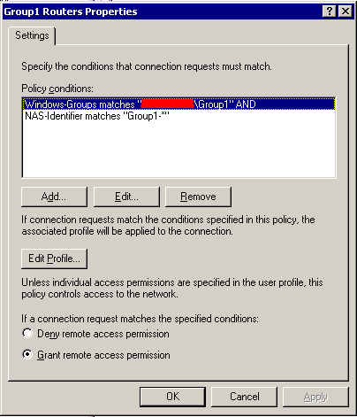
IAS policy filtered by NAS-Identifier attributeFinally we can create two policies in IAS to handle the incoming authentication requests, by filtering them on the basis of NAS-Identifier attribute.
On the NAS-Identifier filter, we can use a star (“*”) to match any character which follows the router’s “tag”. Once we matched the router’s tag, we bind it to the right Active Directory group. Please take a look at the picture for details.

References

Cisco.com: Cisco IOS Security Command Reference, Release 12.3 T

Cisco.com: Command Lookup Tool

PacketLife.net Blog: Seven free ways to improve your network’s security

Kpjungle’s Weblog: Authentication by Radius on a Cisco device

GNS3 Labs: Source-based Remote Triggered Black Hole (RTBH) Filtering with Unicast Reverse Path Forwarding (uRPF)

This post is part of a series about “ISP Security Tools and Techniques“; in this series I talk about some (I think) useful practices:

1. Remote Triggered Black Holing

2. BGP Customer triggered black holing

3. BGP triggered rate limiting and less-than-best-effort (LBE) with QPPB

4. Source-based RTBH with Unicast Reverse Path Forwarding (uRPF)

Stay tuned! 😉

Today I drew inspiration from a brand new RFC to add a post to this little series: RFC-5635, Remote Triggered Black Hole Filtering with Unicast Reverse Path Forwarding (uRPF).

Especially, I would like to focus on section 4 of this RFC, Source Address RTBH Filtering.

To fully understand this post I would suggest to read my previous post Remote Triggered Black Holing.

Read more …

Cisco CEF monitoring with SNMP and CISCO-CEF-MIB

Here I am, back from summer vacation, ready to update my little blog again! 🙂
I would like to talk about another Cisco SNMP MIB…

Starting from release 12.4(20)T IOS offers a powerful tool to manage and monitor enterprise class products performances: SNMP CEF MIB.
CISCO-CEF-MIB is available for large scale Service Provider releases too, such as 12.2(33)SB, but 12.4(20)T is the first release to make it available on low and mid-range products.

The CEF-MIB is quite big and covers a lot of topics about CEF configuration, monitoring and managing; in this topic I will talk about a little, specific branch of this MIB, about stats collection, and how to use it for routers performances monitoring.

MIB structure

As you can see from the Cisco SNMP Object Navigator there are many tables describing CEF: FIB, prefixes, Adjacencies and stats.

In this post I focus on the switching stats table: cefSwitchingStatsTable.

Switching stats table

This table offers statistics related to packets dropping and punting. The CLI command show ip cef switching statistics gives the same view about these stats.

As you know, while packets dropping is not a resource intensive process, packets punting may lead to a huge CPU load, because punted packets need to be switched with a less fast switching method, such as process switching.

cefSwitchingStatsTable
----------------------

# snmpwalk -v 2c -c public -m ALL 192.168.0.8 .1.3.6.1.4.1.9.9.492.1.8.2

CISCO-CEF-MIB::cefSwitchingPath.9.1.1 = STRING: RP RIB
CISCO-CEF-MIB::cefSwitchingPath.9.1.2 = STRING: RP LES
CISCO-CEF-MIB::cefSwitchingPath.9.1.3 = STRING: RP PAS
CISCO-CEF-MIB::cefSwitchingPath.9.2.1 = STRING: RP LES
CISCO-CEF-MIB::cefSwitchingDrop.9.1.1 = Counter32: 0 packets
CISCO-CEF-MIB::cefSwitchingDrop.9.1.2 = Counter32: 0 packets
CISCO-CEF-MIB::cefSwitchingDrop.9.1.3 = Counter32: 3265 packets
CISCO-CEF-MIB::cefSwitchingDrop.9.2.1 = Counter32: 0 packets
CISCO-CEF-MIB::cefSwitchingPunt.9.1.1 = Counter32: 0 packets
CISCO-CEF-MIB::cefSwitchingPunt.9.1.2 = Counter32: 3505 packets
CISCO-CEF-MIB::cefSwitchingPunt.9.1.3 = Counter32: 3506 packets
CISCO-CEF-MIB::cefSwitchingPunt.9.2.1 = Counter32: 0 packets
CISCO-CEF-MIB::cefSwitchingPunt2Host.9.1.1 = Counter32: 0 packets
CISCO-CEF-MIB::cefSwitchingPunt2Host.9.1.2 = Counter32: 0 packets
CISCO-CEF-MIB::cefSwitchingPunt2Host.9.1.3 = Counter32: 8 packets
CISCO-CEF-MIB::cefSwitchingPunt2Host.9.2.1 = Counter32: 0 packets

The table presents an index composed by three elements: entPhysicalIndex, cefFIBIpVersion and cefSwitchingIndex.

The first, entPhysicalIndex, is the value of the entPhysicalTable‘s index (.iso.org.dod.internet.mgmt.mib-2.entityMIB.entityMIBObjects.entityPhysical.entPhysicalTable); it describes the CEF-enabled hardware module the stats refer to.

[...].entPhysicalTable.entPhysicalEntry.entPhysicalDescr.9 = Cisco 7200VXR Network Processing Engine NPE-400
[...].entPhysicalTable.entPhysicalEntry.entPhysicalClass.9 = module
[...].entPhysicalTable.entPhysicalEntry.entPhysicalName.9 = NPE400 0

The second element, cefFIBIpVersion, of type CefIpVersion (see CISCO-CEF-TC MIB), describes the IP protocol: IPv4 (1) or IPv6 (2).

The third, cefSwitchingIndex, is the local identifier: indeed, you may have more switching paths for each module/IP-version.
Switching paths are platform dependent and may be RIB (process switching with CEF assistance), LES (low-end switching CEF), PAS (CEF turbo switch path)… you can find a more comprehensive list on the Cisco Command Lookup Tool, looking for show ip cef switching statistics command.

Why to use CEF monitoring?

To monitor punted packets value, for example by using a SNMP-enabled NMS, may be useful to get an overview about routers and network performances and health, and to lower response time and MTTR in case of degradation. A fast increase on punted packets may be a sign of DOS attacks against routers, or if you have a total packets over punted packets disproportion maybe you have to revise your network design, offloading some work to other routers.

References

Cisco.com: Cisco Express Forwarding SNMP CEF-MIB Support

Cisco.com: Cisco Express Forwarding (CEF)

Cisco.com: CISCO-CEF-MIB
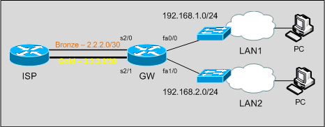
Two LAN distributed on two WAN connections using Policy Based Routing (PBR)

I’m 3 hours from the beginning of my trip to Scotland, but I don’t want to leave unanswered a question that Moh asked me on my previous Dual WAN connection on Cisco with Policy-based routing (PBR) post.

Scenario and Objectives

Scenario and objectives are kindly provided by Moh!

I have a situation same like this, I will give an brief idea. this is for one of my client, they have two leased line connection and using 2801 router it connected to two lan networks(say for 192.168.1.0, 192…2.0/24) they just wanna divide the complete traffic based on internal network. one of the internal(1.0/24) network traffic should go through wan1 (complete traffic, no matter what it is) and other one has (2.0/24) to go through wan2

2 LAN on 2 WAN

Solution

The solution, as in the previous post, is based on PBR (Policy Based Routing). It’s a quite simple use of PBR in this case; as Moh says:

It is very easy to do in fortinet and juniper. but i’m bit confused in cisco now.

Of course, it’s easy using Cisco & IOS too! 😉

I post it here with the hope it could be helpful to someone – other Moh, of course! 🙂

As first, routing policies: what traffic we want to route where?

LAN1 traffic through the Bronze link, LAN2 traffic through the Gold link. We want LAN-to-LAN reachability too.

We define an access list which matches all traffic towards subnets out of our network:

access-list 199 deny   ip any 192.168.0.0 0.0.255.255
access-list 199 permit ip any any

If we don’t exlude 192.168.0.0/16 our route-maps policies will also be applied to LAN-to-LAN traffic.

Then we make route-maps and apply them to LAN interfaces:

route-map LAN1 permit 10
 match ip address 199
 set interface Serial2/0

route-map LAN2 permit 10
 match ip address 199
 set interface Serial2/1

interface FastEthernet0/0
 description LAN1
 ip address 192.168.1.1 255.255.255.0
 ip nat inside
 ip policy route-map LAN1

interface FastEthernet1/0
 description LAN2
 ip address 192.168.2.1 255.255.255.0
 ip nat inside
 ip policy route-map LAN2

Now, routing is Ok; traffic coming from LAN1 with destinations different from LAN2 subnet will be routed out S2/0. Same for LAN2 traffic, out S2/1.

Now, we have to build policy-based NAT: traffic out the S2/0 interface has to be translated using S2/0 IP address; same for traffic coming out from S2/1, translated with S2/1 address.

route-map NAT_LAN1 permit 10
 match interface Serial2/0

route-map NAT_LAN2 permit 10
 match interface Serial2/1

ip nat inside source route-map NAT_LAN1 interface Serial2/0 overload
ip nat inside source route-map NAT_LAN2 interface Serial2/1 overload

Tests

Pings from the LAN (in the GNS3-Lab PCs are routers) to “internet” (4.4.4.4) are routed accordingly to what expected:

GW#sh ip nat translations
Pro Inside global      Inside local       Outside local      Outside global
icmp 2.2.2.2:6         192.168.1.10:6     4.4.4.4:6          4.4.4.4:6
icmp 3.3.3.2:6         192.168.2.10:6     4.4.4.4:6          4.4.4.4:6

If you want to try this in GNS3 please download the lab from the previous post; just few changes are required!

Disclaimer

This post has been written while 85% of my little brain is thinking about Nessie, castle ghosts and left-hand car driving; I hope I didn’t write nonsense!