Tag Archives: GNS3

GNS3 Lab: Remote Triggered Black Holing

This post is part of a series about “ISP Security Tools and Techniques“; in this series I talk about some (I think) useful practices:

1. Remote Triggered Black Holing

2. BGP Customer triggered black holing

3. BGP triggered rate limiting and less-than-best-effort (LBE) with QPPB

4. Source-based RTBH with Unicast Reverse Path Forwarding (uRPF)

Stay tuned! 😉

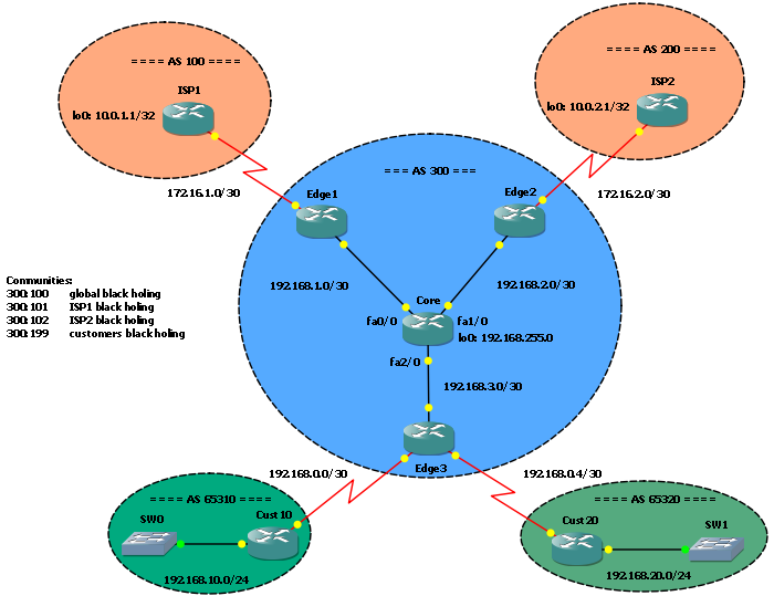
Remote Triggered Black HolingIn this post I would like to talk about Remote Triggered Black Holing, a mechanism to protect a network by filtering malicious traffic at the edge. It’s a powerful tool ISPs can (and should) adopt to stop DDOS attacks on their networks.

UPDATE 2009-06-21: You can find a related solution to use customer triggered blackholing in this new post!

Read more …

GNS3 Lab: BGP – network backdoor, a way to prefer IGP over eBGP

BGP network backdoorThe network … backdoor command let you to prefer IGP over eBGP routing updates without changing the overall BGP administrative distance.

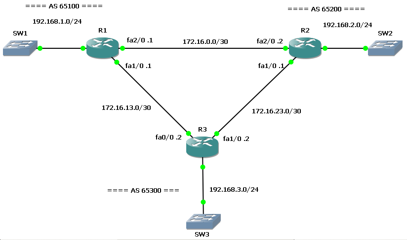
Initially, R1 and R2 run an IGP (EIGRP) on the direct link (172.16.0.0/30).

R1#show ip route | beg Gateway
Gateway of last resort is not set

     172.16.0.0/30 is subnetted, 2 subnets
C       172.16.13.0 is directly connected, FastEthernet1/0
C       172.16.0.0 is directly connected, FastEthernet2/0
C    192.168.1.0/24 is directly connected, FastEthernet0/0
D    192.168.2.0/24 [90/30720] via 172.16.0.2, 00:00:20, FastEthernet2/0

Look at D 192.168.2.0/24 [90/30720] via 172.16.0.2, 00:00:20, FastEthernet2/0.

Then, they start an eBGP peering session with R3…

R3#sh ip bgp
BGP table version is 10, local router ID is 192.168.3.1
Status codes: s suppressed, d damped, h history, * valid, > best, i - internal,
              r RIB-failure, S Stale
Origin codes: i - IGP, e - EGP, ? - incomplete

   Network          Next Hop            Metric LocPrf Weight Path
*> 192.168.1.0      172.16.13.1              0             0 65100 i
*> 192.168.2.0      172.16.23.1              0             0 65200 i
*> 192.168.3.0      0.0.0.0                  0         32768 i

At this time, both R1 and R2 have an eBGP session with R3 and advertise their local networks: 192.168.1.0/24 and 192.168.2.0/24.
Now, looking at R1 (or R2) routing table, we can see they reach each other via R3:

R1#show ip route | beg Gateway
Gateway of last resort is not set

     172.16.0.0/30 is subnetted, 2 subnets
C       172.16.13.0 is directly connected, FastEthernet1/0
C       172.16.0.0 is directly connected, FastEthernet2/0
C    192.168.1.0/24 is directly connected, FastEthernet0/0
B    192.168.2.0/24 [20/0] via 172.16.13.2, 00:02:16
B    192.168.3.0/24 [20/0] via 172.16.13.2, 00:02:16

Look at B 192.168.2.0/24 [20/0] via 172.16.13.2, 00:02:16

Why? What appened? This is not an optimal routing plan!

With BGP peering on, R3 receives R1 (and R2) networks, then it advertise them back to the other peer: the eBGP administrative distance is lower than IGP (EIGRP and others), so R2 (and R1) prefer the route through R3.

To avoid this behaviour you can change BGP administrative distance with distance bgp command, but this is not recommended… or you can use the network backdoor command.

You can apply this command on one peer to tell it to prefer IGP for a given network:

R1(config)#router bgp 65100
R1(config-router)#network 192.168.2.0 mask 255.255.255.0 backdoor

R2(config)#router bgp 65200
R2(config-router)#network 192.168.1.0 mask 255.255.255.0 backdoor

Now back to the routing tables:

R1#show ip route | beg Gateway
Gateway of last resort is not set

     172.16.0.0/30 is subnetted, 2 subnets
C       172.16.13.0 is directly connected, FastEthernet1/0
C       172.16.0.0 is directly connected, FastEthernet2/0
C    192.168.1.0/24 is directly connected, FastEthernet0/0
D    192.168.2.0/24 [90/30720] via 172.16.0.2, 00:00:30, FastEthernet2/0
B    192.168.3.0/24 [20/0] via 172.16.13.2, 00:10:29

The route is again reached via the local link!

If the R1-R2 link goes down…

R2#conf t
Enter configuration commands, one per line.  End with CNTL/Z.
R2(config)#int fa2/0
R2(config-if)#shu
R2(config-if)#shutdown
R2(config-if)#
*Mar  1 00:21:13.195: %DUAL-5-NBRCHANGE: IP-EIGRP(0) 65100: Neighbor 172.16.0.1 (FastEthernet2/0) is down: interface down
*Mar  1 00:21:15.059: %LINK-5-CHANGED: Interface FastEthernet2/0, changed state to administratively down
*Mar  1 00:21:16.059: %LINEPROTO-5-UPDOWN: Line protocol on Interface FastEthernet2/0, changed state to down

… the R2’s network is still reachable via R3:

R1#show ip route | beg Gateway
Gateway of last resort is not set

     172.16.0.0/30 is subnetted, 2 subnets
C       172.16.13.0 is directly connected, FastEthernet1/0
C       172.16.0.0 is directly connected, FastEthernet2/0
C    192.168.1.0/24 is directly connected, FastEthernet0/0
B    192.168.2.0/24 [200/0] via 172.16.13.2, 00:00:17
B    192.168.3.0/24 [20/0] via 172.16.13.2, 00:11:43

You can find on the .zip file 3 config versions (config subdir): “1. Interfaces and IP”, “2. EIGRP + BGP” and the final configuration with the network … backdoor command.

Download the lab here!

GNS3 Lab: BGP – Multihoming to a Single Provider with partial routing

Recently I decided to deepen my knowledge of BGP and MPLS, so I started studying for CCIP certification, which cover both arguments. As suggested by many people I started with BGP “Internet Routing Architectures 2nd Edition”, by Sam Halabi, Cisco Press. It seems to be a really good book, and It contains a lot of scenarios, so I have though to build some GNS3 labs inspired by them. The first interesting one is on chapter 7, Scenario 2, and I tried to build a lab on it.

EDIT 2010-09-07: thanks to a friend, Akuavi Dossou, I found an error in the previous .ZIP file. Cust1_SF and Cust1_NY configurations in the “Base” directory were wrong, 192.168.3.0/30 IP addresses were assigned to the S0/1 interfaces instead of E1/1 and iBGP between the routers didn’t come up. Configurations in the “Final” directory were OK. I fixed the error and uploaded the new .ZIP file. Sorry for the unexpected troubleshooting exercise. 🙂
BGP - Multihoming to a Single Provider with partial routing

BGP - Multihoming to a Single Provider with partial routing

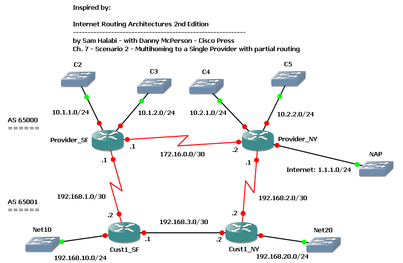
We have a customer with 2 routers multihomed to a single provider: customer’s SF router is connected to provider’s SF router, customer NY router to provider NY router. Customer is in AS 65001, provider in AS 65000. Both customer and provider have an internal link connecting their routers. Provider has some other customers directly connected to its routers, and it’s connected to a NAP through the NY router.

We want our customer to have an optimal routing table to reach both provider’s customers and the full Internet.

We start configuring BGP on the routers; provider’s routers are already configured for iBGP, so we just have to enable the customer neighbors:

Provider_SF(config)#router bgp 65000
Provider_SF(config-router)#neighbor 192.168.1.2 remote-as 65001
Provider_NY(config)#router bgp 65000
Provider_NY(config-router)#neighbor 192.168.2.2 remote-as 65001

Customer’s routers need to be configured for both iBGP and eBGP:

Cust1_SF(config)#router bgp 65001
Cust1_SF(config-router)#network 192.168.10.0
Cust1_SF(config-router)#neighbor 192.168.1.1 remote-as 65000
Cust1_SF(config-router)#neighbor 192.168.3.2 remote-as 65001
Cust1_SF(config-router)#neighbor 192.168.3.2 next-hop-self
Cust1_NY(config)#router bgp 65001
Cust1_NY(config-router)#network 192.168.20.0
Cust1_NY(config-router)#neighbor 192.168.2.1 remote-as 65000
Cust1_NY(config-router)#neighbor 192.168.3.1 remote-as 65001
Cust1_NY(config-router)#neighbor 192.168.3.1 next-hop-self

As soon as BGP sessions come up and are stable, we can take a look at the customer’s routing table:

Cust1_SF#show ip route bgp
     1.0.0.0/24 is subnetted, 1 subnets
B       1.1.1.0 [20/0] via 192.168.1.1, 00:27:53
B    192.168.20.0/24 [200/0] via 192.168.3.2, 00:19:03
     10.0.0.0/24 is subnetted, 4 subnets
B       10.2.1.0 [20/0] via 192.168.1.1, 00:27:53
B       10.1.2.0 [20/0] via 192.168.1.1, 00:27:53
B       10.2.2.0 [20/0] via 192.168.1.1, 00:27:53
B       10.1.1.0 [20/0] via 192.168.1.1, 00:27:53
Cust1_NY#show ip route bgp
     1.0.0.0/24 is subnetted, 1 subnets
B       1.1.1.0 [20/0] via 192.168.2.1, 00:21:18
B    192.168.10.0/24 [200/0] via 192.168.3.1, 00:19:29
     10.0.0.0/24 is subnetted, 4 subnets
B       10.2.1.0 [20/0] via 192.168.2.1, 00:21:18
B       10.1.2.0 [20/0] via 192.168.2.1, 00:21:18
B       10.2.2.0 [20/0] via 192.168.2.1, 00:21:18
B       10.1.1.0 [20/0] via 192.168.2.1, 00:21:18

As we can see, all routes are in the table, but an half of them is using a suboptimal path: remote subnets are reached via the local BGP peer, and this is not good for those directly connected to the other peer. For example, SF customer router should reach C4 and C5 via the internal path to NY router, and then through the Customer_NY-Provider_NY link.

Let’s take a look at the provider’s routing table too:

Provider_SF#sh ip route bgp
     1.0.0.0/24 is subnetted, 1 subnets
B       1.1.1.0 [200/0] via 172.16.0.2, 00:01:59
B    192.168.10.0/24 [20/0] via 192.168.1.2, 00:02:03
B    192.168.20.0/24 [20/0] via 192.168.1.2, 00:01:32
     10.0.0.0/24 is subnetted, 4 subnets
B       10.2.1.0 [200/0] via 172.16.0.2, 00:01:59
B       10.2.2.0 [200/0] via 172.16.0.2, 00:01:59
Provider_NY#sh ip route bgp
B    192.168.10.0/24 [20/0] via 192.168.2.2, 00:02:59
B    192.168.20.0/24 [20/0] via 192.168.2.2, 00:02:59
     10.0.0.0/24 is subnetted, 4 subnets
B       10.1.2.0 [200/0] via 172.16.0.1, 00:02:59
B       10.1.1.0 [200/0] via 172.16.0.1, 00:02:59

Suboptimal paths exist here too: customer’s routes are always reached via the local BGP peer.

Why does BGP prefer routes from the local peer? Let’s get more details about one of these routes:

Cust1_SF#sh ip bgp 10.1.1.0
BGP routing table entry for 10.1.1.0/24, version 2
Paths: (2 available, best #2, table Default-IP-Routing-Table)
  Advertised to update-groups:
     1
  65000
    192.168.3.2 from 192.168.3.2 (192.168.20.1)
      Origin IGP, metric 0, localpref 100, valid, internal
  65000
    192.168.1.1 from 192.168.1.1 (192.168.1.1)
      Origin IGP, metric 0, localpref 100, valid, external, best

Cust1_SF receives C2 subnet (10.1.1.0/24) from Provider_SF (eBGP) and from Cust1_NY (iBGP). Both routes have the same value for all attributes, the only difference is the way they have been learnt: internal (iBGP) and external (eBGP). The BGP decision process picks the external one: this is the rule.

Now it’s time to build an optimal routing table; we want to reach C2 and C3 subnets through SF provider’s router, C4 and C5 through NY router, and unknown destinations (1.1.1.0/24) via NY router too.

On the customer’s side we can achieve this objective by setting different LocalPref values on prefixes learnt at the AS border: SF router will set C2 and C3 with LocalPref = 300, other prefixes with LocalPref = 200; NY router will set C4 and C5 with LocalPref = 300, other prefixes with 250. We can do this using route-maps:

Cust1_SF:

ip prefix-list C2 seq 5 permit 10.1.1.0/24
ip prefix-list C3 seq 5 permit 10.1.2.0/24
!
route-map EBGP-With-ProviderSF_IN permit 10
 match ip address prefix-list C2 C3
 set local-preference 300
route-map EBGP-With-ProviderSF_IN permit 20
 set local-preference 200
!
router bgp 65001
 neighbor 192.168.1.1 route-map EBGP-With-ProviderSF_IN in

Cust1_NY:

ip prefix-list C4 seq 5 permit 10.2.1.0/24
ip prefix-list C5 seq 5 permit 10.2.2.0/24
!
route-map EBGP-With-ProviderNY_IN permit 10
 match ip address prefix-list C4 C5
 set local-preference 300
route-map EBGP-With-ProviderNY_IN permit 20
 set local-preference 250
!
router bgp 65001
 neighbor 192.168.2.1 route-map EBGP-With-ProviderNY_IN in

A clear ip bgp 65000 command forces BGP to update routes and, now, they are filtered by the route-map. This is the result:

Cust1_SF#show ip route bgp
     1.0.0.0/24 is subnetted, 1 subnets
B       1.1.1.0 [200/0] via 192.168.3.2, 00:10:16
B    192.168.20.0/24 [200/0] via 192.168.3.2, 00:10:45
     10.0.0.0/24 is subnetted, 4 subnets
B       10.2.1.0 [200/0] via 192.168.3.2, 00:10:16
B       10.1.2.0 [20/0] via 192.168.1.1, 00:18:32
B       10.2.2.0 [200/0] via 192.168.3.2, 00:10:16
B       10.1.1.0 [20/0] via 192.168.1.1, 00:18:32
Cust1_NY#show ip route bgp
     1.0.0.0/24 is subnetted, 1 subnets
B       1.1.1.0 [20/0] via 192.168.2.1, 00:10:32
B    192.168.10.0/24 [200/0] via 192.168.3.1, 00:11:01
     10.0.0.0/24 is subnetted, 4 subnets
B       10.2.1.0 [20/0] via 192.168.2.1, 00:10:32
B       10.1.2.0 [200/0] via 192.168.3.1, 00:11:01
B       10.2.2.0 [20/0] via 192.168.2.1, 00:10:32
B       10.1.1.0 [200/0] via 192.168.3.1, 00:11:01

We have wath we needed! But what’s up on the Provider’s side?

Provider_SF#sh ip bgp 192.168.10.0
BGP routing table entry for 192.168.10.0/24, version 21
Paths: (2 available, best #2, table Default-IP-Routing-Table)
  Advertised to update-groups:
     2
  65001
    172.16.0.2 from 172.16.0.2 (192.168.2.1)
      Origin IGP, metric 0, localpref 100, valid, internal
  65001
    192.168.1.2 from 192.168.1.2 (192.168.10.1)
      Origin IGP, metric 0, localpref 100, valid, external, best

Nothing! Each router still prefers local BGP peer to reach customer’s subnets. Our route-maps just set LocalPref on customer’s routers, so their influence is limited to just the way learnt routes are preferred each other. To let the provider use an optimal routing table we can set the MED attribute on outgoing BGP UPDATEs, so that locally connected subnets could have a better (lower) metric than others. As usual, we can do that using route-maps and prefix lists:

Cust1_SF:

ip prefix-list Net10 seq 5 permit 192.168.10.0/24
!
route-map EBGP-With-ProviderSF_OUT permit 10
 match ip address prefix-list Net10
 set metric 200
route-map EBGP-With-ProviderSF_OUT permit 20
 set metric 300
!
router bgp 65001
 neighbor 192.168.1.1 route-map EBGP-With-ProviderSF_OUT out

Cust1_NY:

ip prefix-list Net20 seq 5 permit 192.168.20.0/24
!
route-map EBGP-With-ProviderNY_OUT permit 10
 match ip address prefix-list Net20
 set metric 200
route-map EBGP-With-ProviderNY_OUT permit 20
 set metric 250
!
router bgp 65001
 neighbor 192.168.2.1 route-map EBGP-With-ProviderNY_OUT out

Then:

Cust1_SF#clear ip bgp 65000
Cust1_NY#clear ip bgp 65000

Wait until BGP does its job, then:

Provider_SF#sh ip route bgp | inc 192
B    192.168.10.0/24 [20/200] via 192.168.1.2, 00:06:05
B    192.168.20.0/24 [200/200] via 172.16.0.2, 00:06:04
Provider_NY#sh ip route bgp | inc 192
B    192.168.10.0/24 [200/200] via 172.16.0.1, 00:06:46
B    192.168.20.0/24 [20/200] via 192.168.2.2, 00:06:46

Now our provider reaches our subnets in the way we need.

Our subnets are still received from the local eBGP peer, but with different metrics:

Provider_SF#sh ip bgp | inc 192.168
BGP table version is 29, local router ID is 192.168.1.1
*> 192.168.10.0     192.168.1.2            200             0 65001 i
*>i192.168.20.0     172.16.0.2             200    100      0 65001 i
*                   192.168.1.2            300             0 65001 i

192.168.10.0 is the subnet locally connected to the provider’s router peer, so it has a low metric (200), but 192.168.20.0 is not, so it has a higher metric (300). Provider’s router prefers to reach that subnet via the internal link through the other iBGP peer, which receives the subnet with a lower metric (200) from it’s eBGP peer.

On the lab .ZIP file you can find two configuration sets: base and final. The first contains just a base configuration with IP addresses and iBGP on the provider’s side. The final configuration contains all commands reported in this post.

EDIT 2010-09-07: thanks to a friend, Akuavi Dossou, I found an error in the previous .ZIP file. Cust1_SF and Cust1_NY configurations in the “Base” directory were wrong, 192.168.3.0/30 IP addresses were assigned to the S0/1 interfaces instead of E1/1 and iBGP between the routers didn’t come up. Configurations in the “Final” directory were OK. I fixed the error and uploaded the new .ZIP file. Sorry for the unexpected troubleshooting exercise. 🙂

Download the Lab here.
Dual WAN connection on Cisco with Policy-based routing (PBR)

Often, surfing on networking forums and blogs, I find posts by people asking how to setup dual WAN connection and load-balancing on a single box. They are looking for solutions to have the LAN connected to Internet, VoIP traffic with an acceptable QoS level, most of them have to handle VPN tunnels and DMZ too!

Of course, a good network architect would never consider such solution for this scenario, but when budget is low (or not exists at all) there are not many ways to have all these things running!

In this catastrophic scenario Policy-based routing (PBR) can save us!

Here you can find a little PBR based solution and the GNS3 Lab.

Scenario

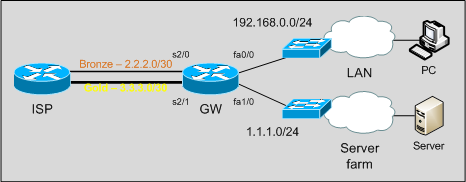
We have a router connected to the ISP with two WAN connections:

– a Bronze link, with little bandwidth, on which we have a /30 subnet;
– a Gold link, with good performances, on which we have a /30 point-to-point subnet and an additional /24 routed subnet.

DualWANScenario

Note that ISP does not accept inbound traffic coming from a subnet that is not the one routed through the ingress interface: for example, we can’t send traffic from 1.1.1.0/24 out the Bronze link. One subnet, one link.

Objectives

Our goals are:

– users on the LAN need access to Internet;
– mission critical traffic has to go out through the Gold link;
– our servers have to be reachable from the outside on their public IP addresses.

For the sake of simplicity, in our example and lab mission critical traffic will be telnet traffic. In real life it can be RTP, database or other important traffic.

At first sight, we can see there is no way to achieve Server farm fault tolerance: if the Gold link goes down, we can’t do anything to keep the subnet reachable. Ok, we can just tell the CIO to get a bigger budget for the network!

Solution

On this topology we have 5 interesting traffic flows:

LAN -> Mission critical services [Gold]
LAN -> WAN [Bronze]
LAN -> Server farm
ServerFarm -> WAN [Gold]
ServerFarm -> LAN

Traffic coming from the LAN towards WAN or Mission Critical Services needs to be translated by NAT too: remember that in the order of operations a packet is first routed, then translated, so actually we can focus just on routing packets out the box in the right way. We will take care about NAT later.

Standard routing just forwards packets on the basis of the destination network; it doesn’t care about Layer 4 properties nor source IP addresses. How can we route traffic on the basis of other elements, such as TCP destination port? If we want to route packets in the expected way we need to deploy Policy Based Routing(PBR). PBR, indeed, can take decisions on the basis of a lot of parameters: source address, destination ports, QoS marking.

Let’s proceed in an orderly fashion.

As first, this is the starting config:

interface Serial2/0
  description Bronze
  ip address 2.2.2.2 255.255.255.252
!
interface Serial2/1
  description Gold
  ip address 3.3.3.2 255.255.255.252
!
interface FastEthernet0/0
  description LAN
  ip address 192.168.0.1 255.255.255.0
!
interface FastEthernet1/0
  description ServerFarm
  ip address 1.1.1.1 255.255.255.0

We just have WAN interfaces up and running and the fastethernet interfaces pointing to the right subnet.

We set default route out to GW through the Bronze link:

ip route 0.0.0.0 0.0.0.0 Serial2/0

With this simple configuration we have already 3 of 5 flows routed in the right way:
– LAN to WAN
– LAN to ServerFarm
– ServerFarm to LAN

Now we need to start our PBR configuration! To do this, we need to create route-maps and then apply them to the ingress interfaces on which policy-based routed packets will enter.

As said, PBR can make decisions on the basis of a lot of elements, such as source address and Layer 4 properties. So, let’s define an access list to match Mission Critical Services (telnet in our example):

ip access-list extended GoldServices
  deny ip any 1.1.1.0 0.0.0.255
  permit tcp any any eq telnet
  deny   ip any any

The access-list just matches telnet traffic that is not directed to our Server farm.

Now we have to define a route-map matching Mission critical traffic and sending it out the Gold link…

route-map PBR_LAN permit 10
  match ip address GoldServices
  set interface Serial2/1 Serial2/0

… then we apply it to the LAN facing interface:

interface FastEthernet0/0
  description LAN
  ip policy route-map PBR_LAN

If a packet doesn’t match any route-map match statement it’s routed on the basis of the standard routing table (so, through the Bronze link).

Note that we used two interface names in the set interface command: if S2/1 is down, IOS will use S2/0, so we have a small level of redundancy and WAN side fault-tolerance for Mission Critical Traffic. We can achieve fault-tolerance for LAN to WAN traffic too by adding an higher metric default route:

ip route 0.0.0.0 0.0.0.0 Serial2/1 10

Now, LAN to Mission Critical Services is OK; we need to do the same for Server farm traffic:

ip access-list extended ServerFarm-To-WAN
  deny   ip 1.1.1.0 0.0.0.255 192.168.0.0 0.0.0.255
  permit ip any any
!
route-map PBR_ServerFarm permit 10
  match ip address ServerFarm-To-WAN
  set interface Serial2/1
!
interface FastEthernet1/0
  description ServerFarm
  ip policy route-map PBR_ServerFarm

Here our access-list does match traffic coming from the server farm to destinations outside the LAN: of course we don’t want to route ServerFarm-to-LAN traffic though the WAN! Unfortunately we can’t add a second interface to the set interface command: our ISP will not accept traffic coming from 1.1.1.0 on the bronze link.

Routing is OK, let’s take care about NAT.

We have 1 inside interface (the LAN facing fastethernet) and 2 outside interfaces:

interface FastEthernet0/0
  description LAN
  ip nat inside
!
interface Serial2/0
  description Bronze
  ip nat outside
!
interface Serial2/1
  description Gold
  ip nat outside

Here we don’t have to think about “policy-based NAT”: when NATting, policies have already been applied, and packets routed accordingly. We just have to translate them in the right way!

As first define the pool to use when translating Gold packets:

ip nat pool LAN-to-Gold 1.1.1.20 1.1.1.20 netmask 255.255.255.0

Then define 2 new route-maps, used in the ip nat inside source command:

route-map NAT_Gold permit 10
  match ip address LAN
  match interface Serial2/1
!
route-map NAT_Bronze permit 10
  match ip address LAN
  match interface Serial2/0

Finally:

ip nat inside source route-map NAT_Gold pool LAN-to-Gold overload
ip nat inside source route-map NAT_Bronze interface Serial2/0 overload

Both route-maps does match 192.168.0.0/24 traffic, but the first (NAT_Gold) takes care only of those packets routed through the s2/1 interface, while the second (NAT_Bronze) of packets routed through the Bronze interface. In this way we are sure the right inside global IP address will be used when translating.

Some tests… on the GNS3 Lab PC and Server are two routers:

traceroute and telnet from PC to “internet” (4.4.4.4 is a ISP loopback):

PC#traceroute 4.4.4.4 n
 Type escape sequence to abort.
 Tracing the route to 4.4.4.4
   1 192.168.0.1 68 msec 40 msec 16 msec
   2 2.2.2.1 120 msec *  52 msec
PC#
PC#telnet 4.4.4.4
 Trying 4.4.4.4 ... Open

 User Access Verification

 Password:

On the gateway, traceroute traffic is translated to 2.2.2.2 (Bronze link) while telnet to 1.1.1.20 (Gold link):

GW#show ip nat translations
Pro Inside global      Inside local       Outside local      Outside global
tcp 1.1.1.20:46878     192.168.0.10:46878 4.4.4.4:23         4.4.4.4:23
udp 2.2.2.2:49178      192.168.0.10:49178 4.4.4.4:33437      4.4.4.4:33437
udp 2.2.2.2:49179      192.168.0.10:49179 4.4.4.4:33438      4.4.4.4:33438
udp 2.2.2.2:49180      192.168.0.10:49180 4.4.4.4:33439      4.4.4.4:33439

A traceroute from the server, going through the Gold link:

Server#traceroute 4.4.4.4 n
Type escape sequence to abort.
Tracing the route to 4.4.4.4
  1 1.1.1.1 72 msec 52 msec 12 msec
  2 3.3.3.1 68 msec *  88 msec
Server#

You can download GNS3-Lab from GNS3-Labs.com: http://www.gns3-labs.com/2009/04/14/gns3-topology-dual-wan-connection-on-cisco-with-policy-based-routing-pbr/

GNS3 Lab: Core and 2 distribution blocks with L3 and L2 access switches

Core and 2 distribution blocks with L3 and L2 access switches

Core and 2 distribution blocks with L3 and L2 access switches

Feature of Topology

L2/L3 switching, VLan, HSRP, GLBP, spanning-tree, trunking, etherchannel, EIGRP, L2/L3 access switches, spanning vlan.

Open this lab on GNS3-Labs.com