Tag Archives: LinkedIn

ACS URL configuration via DHCP Vendor Specific Information

As stated in TR-069, a CPE has 3 ways to know about the ACS URL it has to use for configuration and management; 2 of these ways are not very exciting, while the remaining one opens interesting scenarios for a true plug-and-play deployment.

The not less interesting ACS configuration methods expect the URL to be built-in in the CPE (by factory, for example), or to be configured locally via a LAN-side CPE auto-configuration protocol.

The really interesting method is based on DHCP. Anyway, a CPE doesn’t need to implement this or other methods to be TR-069 compliant; all of them are optional.

Operations

A CPE which implements this mechanism sends a DHCP Request with the string “dslforum.org” in the Vendor Class Identifier (DHCP option 60); at this point, the DHCP server can send back a DHCP ACK with the Vendor Specific Information (DHCP option 43) containing CWMP informations.

This option lets DHCP servers to send one or more vendor specific parameters to clients, encoded in the form option_code/value_length/value; CWMP specifies two parameters: option code 1 for ACS URL and option code 2 for the ProvisioningCode.

When CPE receive the URL it can start the standard CWMP connection and operations with the given ACS.

Applications

The use of this mechanism let us to build interesting scenarios: you can deploy CPEs at the customer sites without a line of configuration, you can bind CPEs CWMP ID to a customer and let DHCP/ACS do the rest, or interact with a RADIUS server to obtain the circuit ID by the IP address and automatically bind it to the right customer.

Configurations

Microsoft Windows Server 2003

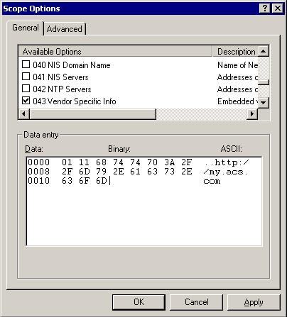
DHCP Option 43 on Win2K3 for ACS URL To setup your Microsoft Windows Server 2003 box to send DHCP Option 43 you have to edit the Scope Options and configure it in a way like the one you can see in the image (click to enlarge). To reach this window, you have to open the DHCP management console from the Administrative Tools, then expand the Superscope and the Scope you want to apply the option to. In the example, we used the URL http://my.acs.com.

dhcpd

To configure dhcpd, you can use the option vendor-encapsulated-options option:

subnet 192.168.0.0 netmask 255.255.255.0 {
        option routers 192.168.0.1;
        range 192.168.0.100 192.168.0.105;
        append dhcp-parameter-request-list 43;
        option vendor-encapsulated-options 01:11:68:74:74:70:3A:2F:2F:61:63:73:2E:6D:65:2E:63:6F:6D;
}

In any case you have to remember the 3 fields: option_code, value_length and value.
In this example we use http://acs.me.com as ACS URL, so our option will contain 0x01 (CWMP option for ACS URL), 0x11 (hex of decimal 17 = length of the URL) then the other 17 bytes forming the URL.

You may ask: why the append dhcp-parameter-request-list 43?;
Well, I tested this ACS discovery mechanism with an AVM Fritz!Box Fon 7170 firmware 58.04.67 at its factory settings; I plugged the LAN cable on its LAN1 interface then I powered it up. When it sends its DHCP REQUEST, it does not insert option 43 in the Parameter Request List, so dhcpd doesn’t send it back to the CPE. The above command tells dhcpd to always send option 43 in the OFFER/ACK.

References

TR-069 at Boadband Forum, par. “3.1 ACS Discovery”;

RFC2132 – DHCP Options and BOOTP Vendor Extensions, par. “8.4. Vendor Specific Information”.

GNS3 Lab: BGP – Multihoming to a Single Provider with partial routing

Recently I decided to deepen my knowledge of BGP and MPLS, so I started studying for CCIP certification, which cover both arguments. As suggested by many people I started with BGP “Internet Routing Architectures 2nd Edition”, by Sam Halabi, Cisco Press. It seems to be a really good book, and It contains a lot of scenarios, so I have though to build some GNS3 labs inspired by them. The first interesting one is on chapter 7, Scenario 2, and I tried to build a lab on it.

EDIT 2010-09-07: thanks to a friend, Akuavi Dossou, I found an error in the previous .ZIP file. Cust1_SF and Cust1_NY configurations in the “Base” directory were wrong, 192.168.3.0/30 IP addresses were assigned to the S0/1 interfaces instead of E1/1 and iBGP between the routers didn’t come up. Configurations in the “Final” directory were OK. I fixed the error and uploaded the new .ZIP file. Sorry for the unexpected troubleshooting exercise. 🙂
BGP - Multihoming to a Single Provider with partial routing

BGP - Multihoming to a Single Provider with partial routing

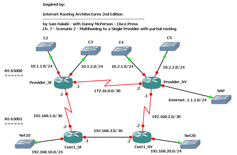
We have a customer with 2 routers multihomed to a single provider: customer’s SF router is connected to provider’s SF router, customer NY router to provider NY router. Customer is in AS 65001, provider in AS 65000. Both customer and provider have an internal link connecting their routers. Provider has some other customers directly connected to its routers, and it’s connected to a NAP through the NY router.

We want our customer to have an optimal routing table to reach both provider’s customers and the full Internet.

We start configuring BGP on the routers; provider’s routers are already configured for iBGP, so we just have to enable the customer neighbors:

Provider_SF(config)#router bgp 65000
Provider_SF(config-router)#neighbor 192.168.1.2 remote-as 65001
Provider_NY(config)#router bgp 65000
Provider_NY(config-router)#neighbor 192.168.2.2 remote-as 65001

Customer’s routers need to be configured for both iBGP and eBGP:

Cust1_SF(config)#router bgp 65001
Cust1_SF(config-router)#network 192.168.10.0
Cust1_SF(config-router)#neighbor 192.168.1.1 remote-as 65000
Cust1_SF(config-router)#neighbor 192.168.3.2 remote-as 65001
Cust1_SF(config-router)#neighbor 192.168.3.2 next-hop-self
Cust1_NY(config)#router bgp 65001
Cust1_NY(config-router)#network 192.168.20.0
Cust1_NY(config-router)#neighbor 192.168.2.1 remote-as 65000
Cust1_NY(config-router)#neighbor 192.168.3.1 remote-as 65001
Cust1_NY(config-router)#neighbor 192.168.3.1 next-hop-self

As soon as BGP sessions come up and are stable, we can take a look at the customer’s routing table:

Cust1_SF#show ip route bgp
     1.0.0.0/24 is subnetted, 1 subnets
B       1.1.1.0 [20/0] via 192.168.1.1, 00:27:53
B    192.168.20.0/24 [200/0] via 192.168.3.2, 00:19:03
     10.0.0.0/24 is subnetted, 4 subnets
B       10.2.1.0 [20/0] via 192.168.1.1, 00:27:53
B       10.1.2.0 [20/0] via 192.168.1.1, 00:27:53
B       10.2.2.0 [20/0] via 192.168.1.1, 00:27:53
B       10.1.1.0 [20/0] via 192.168.1.1, 00:27:53
Cust1_NY#show ip route bgp
     1.0.0.0/24 is subnetted, 1 subnets
B       1.1.1.0 [20/0] via 192.168.2.1, 00:21:18
B    192.168.10.0/24 [200/0] via 192.168.3.1, 00:19:29
     10.0.0.0/24 is subnetted, 4 subnets
B       10.2.1.0 [20/0] via 192.168.2.1, 00:21:18
B       10.1.2.0 [20/0] via 192.168.2.1, 00:21:18
B       10.2.2.0 [20/0] via 192.168.2.1, 00:21:18
B       10.1.1.0 [20/0] via 192.168.2.1, 00:21:18

As we can see, all routes are in the table, but an half of them is using a suboptimal path: remote subnets are reached via the local BGP peer, and this is not good for those directly connected to the other peer. For example, SF customer router should reach C4 and C5 via the internal path to NY router, and then through the Customer_NY-Provider_NY link.

Let’s take a look at the provider’s routing table too:

Provider_SF#sh ip route bgp
     1.0.0.0/24 is subnetted, 1 subnets
B       1.1.1.0 [200/0] via 172.16.0.2, 00:01:59
B    192.168.10.0/24 [20/0] via 192.168.1.2, 00:02:03
B    192.168.20.0/24 [20/0] via 192.168.1.2, 00:01:32
     10.0.0.0/24 is subnetted, 4 subnets
B       10.2.1.0 [200/0] via 172.16.0.2, 00:01:59
B       10.2.2.0 [200/0] via 172.16.0.2, 00:01:59
Provider_NY#sh ip route bgp
B    192.168.10.0/24 [20/0] via 192.168.2.2, 00:02:59
B    192.168.20.0/24 [20/0] via 192.168.2.2, 00:02:59
     10.0.0.0/24 is subnetted, 4 subnets
B       10.1.2.0 [200/0] via 172.16.0.1, 00:02:59
B       10.1.1.0 [200/0] via 172.16.0.1, 00:02:59

Suboptimal paths exist here too: customer’s routes are always reached via the local BGP peer.

Why does BGP prefer routes from the local peer? Let’s get more details about one of these routes:

Cust1_SF#sh ip bgp 10.1.1.0
BGP routing table entry for 10.1.1.0/24, version 2
Paths: (2 available, best #2, table Default-IP-Routing-Table)
  Advertised to update-groups:
     1
  65000
    192.168.3.2 from 192.168.3.2 (192.168.20.1)
      Origin IGP, metric 0, localpref 100, valid, internal
  65000
    192.168.1.1 from 192.168.1.1 (192.168.1.1)
      Origin IGP, metric 0, localpref 100, valid, external, best

Cust1_SF receives C2 subnet (10.1.1.0/24) from Provider_SF (eBGP) and from Cust1_NY (iBGP). Both routes have the same value for all attributes, the only difference is the way they have been learnt: internal (iBGP) and external (eBGP). The BGP decision process picks the external one: this is the rule.

Now it’s time to build an optimal routing table; we want to reach C2 and C3 subnets through SF provider’s router, C4 and C5 through NY router, and unknown destinations (1.1.1.0/24) via NY router too.

On the customer’s side we can achieve this objective by setting different LocalPref values on prefixes learnt at the AS border: SF router will set C2 and C3 with LocalPref = 300, other prefixes with LocalPref = 200; NY router will set C4 and C5 with LocalPref = 300, other prefixes with 250. We can do this using route-maps:

Cust1_SF:

ip prefix-list C2 seq 5 permit 10.1.1.0/24
ip prefix-list C3 seq 5 permit 10.1.2.0/24
!
route-map EBGP-With-ProviderSF_IN permit 10
 match ip address prefix-list C2 C3
 set local-preference 300
route-map EBGP-With-ProviderSF_IN permit 20
 set local-preference 200
!
router bgp 65001
 neighbor 192.168.1.1 route-map EBGP-With-ProviderSF_IN in

Cust1_NY:

ip prefix-list C4 seq 5 permit 10.2.1.0/24
ip prefix-list C5 seq 5 permit 10.2.2.0/24
!
route-map EBGP-With-ProviderNY_IN permit 10
 match ip address prefix-list C4 C5
 set local-preference 300
route-map EBGP-With-ProviderNY_IN permit 20
 set local-preference 250
!
router bgp 65001
 neighbor 192.168.2.1 route-map EBGP-With-ProviderNY_IN in

A clear ip bgp 65000 command forces BGP to update routes and, now, they are filtered by the route-map. This is the result:

Cust1_SF#show ip route bgp
     1.0.0.0/24 is subnetted, 1 subnets
B       1.1.1.0 [200/0] via 192.168.3.2, 00:10:16
B    192.168.20.0/24 [200/0] via 192.168.3.2, 00:10:45
     10.0.0.0/24 is subnetted, 4 subnets
B       10.2.1.0 [200/0] via 192.168.3.2, 00:10:16
B       10.1.2.0 [20/0] via 192.168.1.1, 00:18:32
B       10.2.2.0 [200/0] via 192.168.3.2, 00:10:16
B       10.1.1.0 [20/0] via 192.168.1.1, 00:18:32
Cust1_NY#show ip route bgp
     1.0.0.0/24 is subnetted, 1 subnets
B       1.1.1.0 [20/0] via 192.168.2.1, 00:10:32
B    192.168.10.0/24 [200/0] via 192.168.3.1, 00:11:01
     10.0.0.0/24 is subnetted, 4 subnets
B       10.2.1.0 [20/0] via 192.168.2.1, 00:10:32
B       10.1.2.0 [200/0] via 192.168.3.1, 00:11:01
B       10.2.2.0 [20/0] via 192.168.2.1, 00:10:32
B       10.1.1.0 [200/0] via 192.168.3.1, 00:11:01

We have wath we needed! But what’s up on the Provider’s side?

Provider_SF#sh ip bgp 192.168.10.0
BGP routing table entry for 192.168.10.0/24, version 21
Paths: (2 available, best #2, table Default-IP-Routing-Table)
  Advertised to update-groups:
     2
  65001
    172.16.0.2 from 172.16.0.2 (192.168.2.1)
      Origin IGP, metric 0, localpref 100, valid, internal
  65001
    192.168.1.2 from 192.168.1.2 (192.168.10.1)
      Origin IGP, metric 0, localpref 100, valid, external, best

Nothing! Each router still prefers local BGP peer to reach customer’s subnets. Our route-maps just set LocalPref on customer’s routers, so their influence is limited to just the way learnt routes are preferred each other. To let the provider use an optimal routing table we can set the MED attribute on outgoing BGP UPDATEs, so that locally connected subnets could have a better (lower) metric than others. As usual, we can do that using route-maps and prefix lists:

Cust1_SF:

ip prefix-list Net10 seq 5 permit 192.168.10.0/24
!
route-map EBGP-With-ProviderSF_OUT permit 10
 match ip address prefix-list Net10
 set metric 200
route-map EBGP-With-ProviderSF_OUT permit 20
 set metric 300
!
router bgp 65001
 neighbor 192.168.1.1 route-map EBGP-With-ProviderSF_OUT out

Cust1_NY:

ip prefix-list Net20 seq 5 permit 192.168.20.0/24
!
route-map EBGP-With-ProviderNY_OUT permit 10
 match ip address prefix-list Net20
 set metric 200
route-map EBGP-With-ProviderNY_OUT permit 20
 set metric 250
!
router bgp 65001
 neighbor 192.168.2.1 route-map EBGP-With-ProviderNY_OUT out

Then:

Cust1_SF#clear ip bgp 65000
Cust1_NY#clear ip bgp 65000

Wait until BGP does its job, then:

Provider_SF#sh ip route bgp | inc 192
B    192.168.10.0/24 [20/200] via 192.168.1.2, 00:06:05
B    192.168.20.0/24 [200/200] via 172.16.0.2, 00:06:04
Provider_NY#sh ip route bgp | inc 192
B    192.168.10.0/24 [200/200] via 172.16.0.1, 00:06:46
B    192.168.20.0/24 [20/200] via 192.168.2.2, 00:06:46

Now our provider reaches our subnets in the way we need.

Our subnets are still received from the local eBGP peer, but with different metrics:

Provider_SF#sh ip bgp | inc 192.168
BGP table version is 29, local router ID is 192.168.1.1
*> 192.168.10.0     192.168.1.2            200             0 65001 i
*>i192.168.20.0     172.16.0.2             200    100      0 65001 i
*                   192.168.1.2            300             0 65001 i

192.168.10.0 is the subnet locally connected to the provider’s router peer, so it has a low metric (200), but 192.168.20.0 is not, so it has a higher metric (300). Provider’s router prefers to reach that subnet via the internal link through the other iBGP peer, which receives the subnet with a lower metric (200) from it’s eBGP peer.

On the lab .ZIP file you can find two configuration sets: base and final. The first contains just a base configuration with IP addresses and iBGP on the provider’s side. The final configuration contains all commands reported in this post.

EDIT 2010-09-07: thanks to a friend, Akuavi Dossou, I found an error in the previous .ZIP file. Cust1_SF and Cust1_NY configurations in the “Base” directory were wrong, 192.168.3.0/30 IP addresses were assigned to the S0/1 interfaces instead of E1/1 and iBGP between the routers didn’t come up. Configurations in the “Final” directory were OK. I fixed the error and uploaded the new .ZIP file. Sorry for the unexpected troubleshooting exercise. 🙂

Download the Lab here.
Zabbix tool for Cisco Class-Based QoS monitoring

As said in my previous post about this topic, I’ve made a small Perl script to build Zabbix configuration for Cisco Class-Based QoS monitoring.

As first, I have to say I’m NOT a Perl programmer, so I think real Perl programmers will find my script a shocking jumble of code. I apoligize!

Any suggestion would be appreciate!

Disclaimer

This is a beta version of the script: use it at your own risk!

Download

You can find the script here. It requires Net::SNMP module (“apt-get install libnet-snmp-perl” on Debian to install it).

What it does

This script lets you to monitor Cisco QoS stats and counters in your Zabbix NMS using the builtin SNMP agent. You can store the same stats you can see with a “show policy-map interface …” command and have graphs built on them.

You can get values from class-maps, match statements, traffic policing and shaping.

How it works

When you run the script (with proper arguments!) it walks through the SNMP MIB of your device and discovers QoS policies layout; then, it builds Zabbix items and graphs about objects it finds.

How to use it

Unfortunately Zabbix has a quite complex database structure, so I preferred to use the builtin import/export feature instead of manipulating tables directly in my script to add items and graphs.

The output is formatted on the basis of the Zabbix XML configuration file.

To use the script you have to export your Cisco device configuration from the Zabbix Configuration / Export/Import menu, then merge the script’s output within the <host> XML element and, finally, import the new XML file into Zabbix.

Usage is pretty simple:

./ciscocbqos HOST [-c SNMP_COMMUNITY] -o OUTPUT_PATH OBJECTS_TO_MONITOR

Here, HOST is the Cisco device IP address, SNMP_COMMUNITY is the SNMP read community (default to public), and OBJECTS_TO_MONITOR is a list of one or more objects you want to add to Zabbix (objects are class-maps, match statements, traffic policing and traffic shaping). More options are available: you can see the full help just running ./ciscocbqos without any argument.

For example, if you want to monitor traffic-shaping on router at 192.168.0.1 you can run

./ciscocbqos 192.168.0.1 -c myreadcommunity -o /root/qos +trafficshaping

Once done, you will find /root/qos.items and /root/qos.graphs files containing a scrap of Zabbix XML file to merge with your existing configuration. At this point all you have to do is to put qos.items and qos.graphs content inside the <host> XML element of the exported Zabbix file (line 17 and 18 of the following example).

&lt;?xml version=&quot;1.0&quot;?&gt;
&lt;zabbix_export version=&quot;1.0&quot; date=&quot;21.04.09&quot; time=&quot;17.59&quot;&gt;
	&lt;hosts&gt;
		&lt;host name=&quot;MYCISCODEVICE&quot;&gt;
			&lt;useip&gt;1&lt;/useip&gt;
			&lt;dns&gt;&lt;/dns&gt;
			&lt;ip&gt;192.168.0.1&lt;/ip&gt;
			&lt;port&gt;10050&lt;/port&gt;
			&lt;status&gt;0&lt;/status&gt;
			&lt;groups&gt;
				&lt;group&gt;Router&lt;/group&gt;
			&lt;/groups&gt;
			&lt;templates&gt;
				&lt;template&gt;Template_Cisco_Device&lt;/template&gt;
				&lt;template&gt;Template_MyOwnTemplate&lt;/template&gt;
			&lt;/templates&gt;
			qos.items content goes here
			qos.graphs content goes here
		&lt;/host&gt;
	&lt;/hosts&gt;
	&lt;dependencies&gt;
	&lt;/dependencies&gt;
&lt;/zabbix_export&gt;

Zabbix keys and SNMP indexes

As you know Zabbix uses keys to uniquely identify items within a host; SNMP agent gets those values from devices and stores them using their keys. This script can be ran in two ways to build Zabbix keys: with or without the +p option.

You should use the +p option only if your device has the “snmp mib persist cbqos” command in the configuration. This option lets the script to build keys based on the SNMP indexes: if you use the “snmp mib persist cbqos” command indexes are maintained after device restart.

With no “snmp mib persist cbqos” command in the config, you should run the script without the +p option, in order to build Zabbix keys on the basis of a hash of items descriptions. In this scenario you have to run the script every time you restart your device, cause SNMP indexes will change and Zabbix items will be outdated.

The cbqos keyword was added starting from IOS 12.4(4)T.

Some graphs

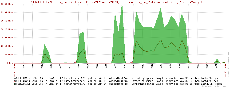
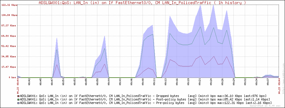
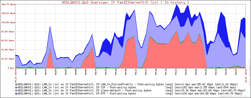
Here are some Zabbix graphs generated using the script:

Traffic policing

Traffic policing

Traffic policing class-map

Traffic policing class-map

Interface overview (stack of class-map)

Interface overview (stack of class-map)

Cisco Class-Based QoS SNMP MIB and statistics monitor for NMS

As stated in the official CISCO-CLASS-BASED-QOS-MIB file, Cisco Class-Based QoS MIB “provides read access to Quality of Service (QoS) configuration and statistics information for Cisco platforms that support the Modular Quality of Service Command-line Interface“.

In other words, the integration of this MIB in a SNMP-based NMS lets you to monitor all the values you can see with the show policy-map IOS command.

This MIB has not a so straightforward structure as other MIBs have, so integration with NMS can be a little diffcult.

Let’s take a deeper look at its structure; in a future post I’ll show how to use this information to monitor IOS QoS statistics in Zabbix.

We’ll use the following trivial IOS configuration for our examples:

class-map match-any NonLocal
 match access-group 10
!
class-map match-all ICMP
 match protocol icmp
!
policy-map CPP
  description Applied to control plan - In
 class NonLocal
   police cir 8000
     conform-action transmit
     exceed-action drop
!
policy-map LAN_Out
  description Applied to fa0/0 - Out
 class ICMP
  bandwidth 10
 class class-default
  fair-queue
!
interface FastEthernet0/0
 ip address 192.168.0.8 255.255.255.0
 service-policy output LAN_Out
!
access-list 10 deny   192.168.0.0 0.0.0.255
access-list 10 permit any
!
control-plane
 service-policy input CPP

In this MIB informations are stored on a lot of tables:

  • cbQosServicePolicyTable and cbQosObjectsTable define QoS policies layout;
  • cbQosXXXCfgTable tables define configuration details for the objects (ClassMap, PolicyMap, Match statements…);
  • cbQosXXXStatsTable tables define runtime statistics for the same objects.

As first, we have to look at cbQosServicePolicyTable: here we find bindings between policy-maps and interfaces, as in the service-policy command:

cbQosServicePolicyTable
-----------------------

# snmpwalk -v 2c -c public -m ALL 192.168.0.8 .1.3.6.1.4.1.9.9.166.1.1.1

CISCO-CLASS-BASED-QOS-MIB::cbQosIfType.1043 = INTEGER: mainInterface(1)
CISCO-CLASS-BASED-QOS-MIB::cbQosIfType.1099 = INTEGER: controlPlane(5)
CISCO-CLASS-BASED-QOS-MIB::cbQosPolicyDirection.1043 = INTEGER: output(2)
CISCO-CLASS-BASED-QOS-MIB::cbQosPolicyDirection.1099 = INTEGER: input(1)
CISCO-CLASS-BASED-QOS-MIB::cbQosIfIndex.1043 = INTEGER: 1
CISCO-CLASS-BASED-QOS-MIB::cbQosIfIndex.1099 = INTEGER: 1
CISCO-CLASS-BASED-QOS-MIB::cbQosFrDLCI.1043 = INTEGER: 0
CISCO-CLASS-BASED-QOS-MIB::cbQosFrDLCI.1099 = INTEGER: 0
CISCO-CLASS-BASED-QOS-MIB::cbQosAtmVPI.1043 = Gauge32: 0
CISCO-CLASS-BASED-QOS-MIB::cbQosAtmVPI.1099 = Gauge32: 0
CISCO-CLASS-BASED-QOS-MIB::cbQosAtmVCI.1043 = Gauge32: 0
CISCO-CLASS-BASED-QOS-MIB::cbQosAtmVCI.1099 = Gauge32: 0
CISCO-CLASS-BASED-QOS-MIB::cbQosEntityIndex.1043 = INTEGER: 0
CISCO-CLASS-BASED-QOS-MIB::cbQosEntityIndex.1099 = INTEGER: 0

cbQosPolicyIndex is the table’s index (1043, 1099 in the previous example); it identifies the service-policy.

cbQosIfType defines the type of interface which the service-policy is applied to: mainInterface(1), subInterface(2), frDLCI(3), atmPVC(4), controlPlane(5), vlanPort(6).

cbQosPolicyDirection tells the direction of the traffic: input(1) and output(2).

Other parameters depend on cbQosIfType value and represent specific objects identifiers (ifIndex, DLCI, VPI/VCI, … ).

From the previous example we can see there are 2 service-policies, with ID 1043 and 1099, applied for output traffic to a physical interface with ifIndex 1, and for input traffic to the control-plane.

The second important table is cbQosObjectsTable, where all objects (class-map, match, set statements…) are stored, classified (cbQosObjectsType), identified within the configuration (cbQosConfigIndex) and related to the service-policy or other objects (cbQosParentObjectsIndex). Here we have a two-fields index: cbQosPolicyIndex and cbQosObjectsIndex:

cbQosObjectsTable
-----------------

# snmpwalk -v 2c -c public -m ALL 192.168.0.8 .1.3.6.1.4.1.9.9.166.1.5.1

CISCO-CLASS-BASED-QOS-MIB::cbQosConfigIndex.1043.1043 = Gauge32: 1035
CISCO-CLASS-BASED-QOS-MIB::cbQosConfigIndex.1043.1045 = Gauge32: 1029
CISCO-CLASS-BASED-QOS-MIB::cbQosConfigIndex.1043.1047 = Gauge32: 1033
CISCO-CLASS-BASED-QOS-MIB::cbQosConfigIndex.1043.1049 = Gauge32: 1037
CISCO-CLASS-BASED-QOS-MIB::cbQosConfigIndex.1043.1051 = Gauge32: 1025
CISCO-CLASS-BASED-QOS-MIB::cbQosConfigIndex.1043.1053 = Gauge32: 1027
CISCO-CLASS-BASED-QOS-MIB::cbQosConfigIndex.1043.1085 = Gauge32: 1079
CISCO-CLASS-BASED-QOS-MIB::cbQosConfigIndex.1099.1099 = Gauge32: 1063
CISCO-CLASS-BASED-QOS-MIB::cbQosConfigIndex.1099.1101 = Gauge32: 1057
CISCO-CLASS-BASED-QOS-MIB::cbQosConfigIndex.1099.1103 = Gauge32: 1061
CISCO-CLASS-BASED-QOS-MIB::cbQosConfigIndex.1099.1105 = Gauge32: 1065
CISCO-CLASS-BASED-QOS-MIB::cbQosConfigIndex.1099.1107 = Gauge32: 1025
CISCO-CLASS-BASED-QOS-MIB::cbQosConfigIndex.1099.1109 = Gauge32: 1027
CISCO-CLASS-BASED-QOS-MIB::cbQosObjectsType.1043.1043 = INTEGER: policymap(1)
CISCO-CLASS-BASED-QOS-MIB::cbQosObjectsType.1043.1045 = INTEGER: classmap(2)
CISCO-CLASS-BASED-QOS-MIB::cbQosObjectsType.1043.1047 = INTEGER: matchStatement(3)
CISCO-CLASS-BASED-QOS-MIB::cbQosObjectsType.1043.1049 = INTEGER: queueing(4)
CISCO-CLASS-BASED-QOS-MIB::cbQosObjectsType.1043.1051 = INTEGER: classmap(2)
CISCO-CLASS-BASED-QOS-MIB::cbQosObjectsType.1043.1053 = INTEGER: matchStatement(3)
CISCO-CLASS-BASED-QOS-MIB::cbQosObjectsType.1043.1085 = INTEGER: queueing(4)
CISCO-CLASS-BASED-QOS-MIB::cbQosObjectsType.1099.1099 = INTEGER: policymap(1)
CISCO-CLASS-BASED-QOS-MIB::cbQosObjectsType.1099.1101 = INTEGER: classmap(2)
CISCO-CLASS-BASED-QOS-MIB::cbQosObjectsType.1099.1103 = INTEGER: matchStatement(3)
CISCO-CLASS-BASED-QOS-MIB::cbQosObjectsType.1099.1105 = INTEGER: police(7)
CISCO-CLASS-BASED-QOS-MIB::cbQosObjectsType.1099.1107 = INTEGER: classmap(2)
CISCO-CLASS-BASED-QOS-MIB::cbQosObjectsType.1099.1109 = INTEGER: matchStatement(3)
CISCO-CLASS-BASED-QOS-MIB::cbQosParentObjectsIndex.1043.1043 = Gauge32: 0
CISCO-CLASS-BASED-QOS-MIB::cbQosParentObjectsIndex.1043.1045 = Gauge32: 1043
CISCO-CLASS-BASED-QOS-MIB::cbQosParentObjectsIndex.1043.1047 = Gauge32: 1045
CISCO-CLASS-BASED-QOS-MIB::cbQosParentObjectsIndex.1043.1049 = Gauge32: 1045
CISCO-CLASS-BASED-QOS-MIB::cbQosParentObjectsIndex.1043.1051 = Gauge32: 1043
CISCO-CLASS-BASED-QOS-MIB::cbQosParentObjectsIndex.1043.1053 = Gauge32: 1051
CISCO-CLASS-BASED-QOS-MIB::cbQosParentObjectsIndex.1043.1085 = Gauge32: 1051
CISCO-CLASS-BASED-QOS-MIB::cbQosParentObjectsIndex.1099.1099 = Gauge32: 0
CISCO-CLASS-BASED-QOS-MIB::cbQosParentObjectsIndex.1099.1101 = Gauge32: 1099
CISCO-CLASS-BASED-QOS-MIB::cbQosParentObjectsIndex.1099.1103 = Gauge32: 1101
CISCO-CLASS-BASED-QOS-MIB::cbQosParentObjectsIndex.1099.1105 = Gauge32: 1101
CISCO-CLASS-BASED-QOS-MIB::cbQosParentObjectsIndex.1099.1107 = Gauge32: 1099
CISCO-CLASS-BASED-QOS-MIB::cbQosParentObjectsIndex.1099.1109 = Gauge32: 1107

cbQosConfigIndex let us to find configuration details about objects in other tables; service-policies have the same cbQosObjectsIndex as cbQosPolicyIndex. These config tables are cbQosObjectsType dependent: we have cbQosPolicyMapCfgTable, cbQosClassMapCfgTable, cbQosMatchStmtCfgTable… each object type has its own table, all referenced by cbQosConfigIndex.

Let’s see one of them…

cbQosPolicyMapCfgTable
----------------------

# snmpwalk -v 2c -c public -m ALL 192.168.0.8 .1.3.6.1.4.1.9.9.166.1.6.1

CISCO-CLASS-BASED-QOS-MIB::cbQosPolicyMapName.1035 = STRING: LAN_Out
CISCO-CLASS-BASED-QOS-MIB::cbQosPolicyMapName.1063 = STRING: CPP
CISCO-CLASS-BASED-QOS-MIB::cbQosPolicyMapDesc.1035 = STRING: Applied to fa0/0 - Out
CISCO-CLASS-BASED-QOS-MIB::cbQosPolicyMapDesc.1063 = STRING: Applied to control plan - In

We can see here our policy-maps, indexed by the cbQosConfigIndex values previously found on cbQosObjectsTable.

With the cbQosObjectsTable data we already have all informations we need to build an OID list for our NMS.

Assume we just need to monitor class-map offered rate and drop rate, as in the show policy-map interface | inc Class-map|offered. All per class-map statistics are collected on the cbQosCMStatsTable; as all stats table, it’s indexed by cbQosPolicyIndex and cbQosObjectsIndex. Take a look at the table:

cbQosCMStatsTable
-----------------

# snmpwalk -v 2c -c public -m ALL 192.168.0.8 .1.3.6.1.4.1.9.9.166.1.15.1.1

CISCO-CLASS-BASED-QOS-MIB::cbQosCMPrePolicyPktOverflow.1043.1045 = Counter32: 0
CISCO-CLASS-BASED-QOS-MIB::cbQosCMPrePolicyPktOverflow.1043.1051 = Counter32: 0
CISCO-CLASS-BASED-QOS-MIB::cbQosCMPrePolicyPktOverflow.1099.1101 = Counter32: 0
CISCO-CLASS-BASED-QOS-MIB::cbQosCMPrePolicyPktOverflow.1099.1107 = Counter32: 0
CISCO-CLASS-BASED-QOS-MIB::cbQosCMPrePolicyPkt.1043.1045 = Counter32: 8
CISCO-CLASS-BASED-QOS-MIB::cbQosCMPrePolicyPkt.1043.1051 = Counter32: 1131
CISCO-CLASS-BASED-QOS-MIB::cbQosCMPrePolicyPkt.1099.1101 = Counter32: 281
CISCO-CLASS-BASED-QOS-MIB::cbQosCMPrePolicyPkt.1099.1107 = Counter32: 7016
CISCO-CLASS-BASED-QOS-MIB::cbQosCMPrePolicyPkt64.1043.1045 = Counter64: 8
CISCO-CLASS-BASED-QOS-MIB::cbQosCMPrePolicyPkt64.1043.1051 = Counter64: 1131
CISCO-CLASS-BASED-QOS-MIB::cbQosCMPrePolicyPkt64.1099.1101 = Counter64: 281
CISCO-CLASS-BASED-QOS-MIB::cbQosCMPrePolicyPkt64.1099.1107 = Counter64: 7016
CISCO-CLASS-BASED-QOS-MIB::cbQosCMPrePolicyByteOverflow.1043.1045 = Counter32: 0
CISCO-CLASS-BASED-QOS-MIB::cbQosCMPrePolicyByteOverflow.1043.1051 = Counter32: 0
CISCO-CLASS-BASED-QOS-MIB::cbQosCMPrePolicyByteOverflow.1099.1101 = Counter32: 0
CISCO-CLASS-BASED-QOS-MIB::cbQosCMPrePolicyByteOverflow.1099.1107 = Counter32: 0
CISCO-CLASS-BASED-QOS-MIB::cbQosCMPrePolicyByte.1043.1045 = Counter32: 784
CISCO-CLASS-BASED-QOS-MIB::cbQosCMPrePolicyByte.1043.1051 = Counter32: 114630
CISCO-CLASS-BASED-QOS-MIB::cbQosCMPrePolicyByte.1099.1101 = Counter32: 69858
CISCO-CLASS-BASED-QOS-MIB::cbQosCMPrePolicyByte.1099.1107 = Counter32: 658800
CISCO-CLASS-BASED-QOS-MIB::cbQosCMPrePolicyByte64.1043.1045 = Counter64: 784
CISCO-CLASS-BASED-QOS-MIB::cbQosCMPrePolicyByte64.1043.1051 = Counter64: 114630
CISCO-CLASS-BASED-QOS-MIB::cbQosCMPrePolicyByte64.1099.1101 = Counter64: 69858
CISCO-CLASS-BASED-QOS-MIB::cbQosCMPrePolicyByte64.1099.1107 = Counter64: 658800
CISCO-CLASS-BASED-QOS-MIB::cbQosCMPrePolicyBitRate.1043.1045 = Gauge32: 0 bits per second
CISCO-CLASS-BASED-QOS-MIB::cbQosCMPrePolicyBitRate.1043.1051 = Gauge32: 0 bits per second
CISCO-CLASS-BASED-QOS-MIB::cbQosCMPrePolicyBitRate.1099.1101 = Gauge32: 0 bits per second
CISCO-CLASS-BASED-QOS-MIB::cbQosCMPrePolicyBitRate.1099.1107 = Gauge32: 1000 bits per second
CISCO-CLASS-BASED-QOS-MIB::cbQosCMPostPolicyByteOverflow.1043.1045 = Counter32: 0
CISCO-CLASS-BASED-QOS-MIB::cbQosCMPostPolicyByteOverflow.1043.1051 = Counter32: 0
CISCO-CLASS-BASED-QOS-MIB::cbQosCMPostPolicyByteOverflow.1099.1101 = Counter32: 0
CISCO-CLASS-BASED-QOS-MIB::cbQosCMPostPolicyByteOverflow.1099.1107 = Counter32: 0
CISCO-CLASS-BASED-QOS-MIB::cbQosCMPostPolicyByte.1043.1045 = Counter32: 784
CISCO-CLASS-BASED-QOS-MIB::cbQosCMPostPolicyByte.1043.1051 = Counter32: 114630
CISCO-CLASS-BASED-QOS-MIB::cbQosCMPostPolicyByte.1099.1101 = Counter32: 69668
CISCO-CLASS-BASED-QOS-MIB::cbQosCMPostPolicyByte.1099.1107 = Counter32: 658800
CISCO-CLASS-BASED-QOS-MIB::cbQosCMPostPolicyByte64.1043.1045 = Counter64: 784
CISCO-CLASS-BASED-QOS-MIB::cbQosCMPostPolicyByte64.1043.1051 = Counter64: 114630
CISCO-CLASS-BASED-QOS-MIB::cbQosCMPostPolicyByte64.1099.1101 = Counter64: 69668
CISCO-CLASS-BASED-QOS-MIB::cbQosCMPostPolicyByte64.1099.1107 = Counter64: 658800
CISCO-CLASS-BASED-QOS-MIB::cbQosCMPostPolicyBitRate.1043.1045 = Gauge32: 0 bits per second
CISCO-CLASS-BASED-QOS-MIB::cbQosCMPostPolicyBitRate.1043.1051 = Gauge32: 2000 bits per second
CISCO-CLASS-BASED-QOS-MIB::cbQosCMPostPolicyBitRate.1099.1101 = Gauge32: 2000 bits per second
CISCO-CLASS-BASED-QOS-MIB::cbQosCMPostPolicyBitRate.1099.1107 = Gauge32: 2000 bits per second
CISCO-CLASS-BASED-QOS-MIB::cbQosCMDropPktOverflow.1043.1045 = Counter32: 0
CISCO-CLASS-BASED-QOS-MIB::cbQosCMDropPktOverflow.1043.1051 = Counter32: 0
CISCO-CLASS-BASED-QOS-MIB::cbQosCMDropPktOverflow.1099.1101 = Counter32: 0
CISCO-CLASS-BASED-QOS-MIB::cbQosCMDropPktOverflow.1099.1107 = Counter32: 0
CISCO-CLASS-BASED-QOS-MIB::cbQosCMDropPkt.1043.1045 = Counter32: 0
CISCO-CLASS-BASED-QOS-MIB::cbQosCMDropPkt.1043.1051 = Counter32: 0
CISCO-CLASS-BASED-QOS-MIB::cbQosCMDropPkt.1099.1101 = Counter32: 4
CISCO-CLASS-BASED-QOS-MIB::cbQosCMDropPkt.1099.1107 = Counter32: 0
CISCO-CLASS-BASED-QOS-MIB::cbQosCMDropPkt64.1043.1045 = Counter64: 0
CISCO-CLASS-BASED-QOS-MIB::cbQosCMDropPkt64.1043.1051 = Counter64: 0
CISCO-CLASS-BASED-QOS-MIB::cbQosCMDropPkt64.1099.1101 = Counter64: 4
CISCO-CLASS-BASED-QOS-MIB::cbQosCMDropPkt64.1099.1107 = Counter64: 0
CISCO-CLASS-BASED-QOS-MIB::cbQosCMDropByteOverflow.1043.1045 = Counter32: 0
CISCO-CLASS-BASED-QOS-MIB::cbQosCMDropByteOverflow.1043.1051 = Counter32: 0
CISCO-CLASS-BASED-QOS-MIB::cbQosCMDropByteOverflow.1099.1101 = Counter32: 0
CISCO-CLASS-BASED-QOS-MIB::cbQosCMDropByteOverflow.1099.1107 = Counter32: 0
CISCO-CLASS-BASED-QOS-MIB::cbQosCMDropByte.1043.1045 = Counter32: 0
CISCO-CLASS-BASED-QOS-MIB::cbQosCMDropByte.1043.1051 = Counter32: 0
CISCO-CLASS-BASED-QOS-MIB::cbQosCMDropByte.1099.1101 = Counter32: 380
CISCO-CLASS-BASED-QOS-MIB::cbQosCMDropByte.1099.1107 = Counter32: 0
CISCO-CLASS-BASED-QOS-MIB::cbQosCMDropByte64.1043.1045 = Counter64: 0
CISCO-CLASS-BASED-QOS-MIB::cbQosCMDropByte64.1043.1051 = Counter64: 0
CISCO-CLASS-BASED-QOS-MIB::cbQosCMDropByte64.1099.1101 = Counter64: 380
CISCO-CLASS-BASED-QOS-MIB::cbQosCMDropByte64.1099.1107 = Counter64: 0
CISCO-CLASS-BASED-QOS-MIB::cbQosCMDropBitRate.1043.1045 = Gauge32: 0 bits per second
CISCO-CLASS-BASED-QOS-MIB::cbQosCMDropBitRate.1043.1051 = Gauge32: 0 bits per second
CISCO-CLASS-BASED-QOS-MIB::cbQosCMDropBitRate.1099.1101 = Gauge32: 0 bits per second
CISCO-CLASS-BASED-QOS-MIB::cbQosCMDropBitRate.1099.1107 = Gauge32: 0 bits per second
CISCO-CLASS-BASED-QOS-MIB::cbQosCMNoBufDropPktOverflow.1043.1045 = Counter32: 0
CISCO-CLASS-BASED-QOS-MIB::cbQosCMNoBufDropPktOverflow.1043.1051 = Counter32: 0
CISCO-CLASS-BASED-QOS-MIB::cbQosCMNoBufDropPktOverflow.1099.1101 = Counter32: 0
CISCO-CLASS-BASED-QOS-MIB::cbQosCMNoBufDropPktOverflow.1099.1107 = Counter32: 0
CISCO-CLASS-BASED-QOS-MIB::cbQosCMNoBufDropPkt.1043.1045 = Counter32: 0
CISCO-CLASS-BASED-QOS-MIB::cbQosCMNoBufDropPkt.1043.1051 = Counter32: 0
CISCO-CLASS-BASED-QOS-MIB::cbQosCMNoBufDropPkt.1099.1101 = Counter32: 0
CISCO-CLASS-BASED-QOS-MIB::cbQosCMNoBufDropPkt.1099.1107 = Counter32: 0
CISCO-CLASS-BASED-QOS-MIB::cbQosCMNoBufDropPkt64.1043.1045 = Counter64: 0
CISCO-CLASS-BASED-QOS-MIB::cbQosCMNoBufDropPkt64.1043.1051 = Counter64: 0
CISCO-CLASS-BASED-QOS-MIB::cbQosCMNoBufDropPkt64.1099.1101 = Counter64: 0
CISCO-CLASS-BASED-QOS-MIB::cbQosCMNoBufDropPkt64.1099.1107 = Counter64: 0

We just need to select cbQosPolicyIndex and cbQosObjectsIndex values from cbQosObjectsTable where cbQosObjectsType = classmap(2) and attach them to the counter we need to monitor.

CISCO-CLASS-BASED-QOS-MIB::cbQosCMPrePolicyBitRate.1043.1045 = Gauge32: 0 bits per second
CISCO-CLASS-BASED-QOS-MIB::cbQosCMPrePolicyBitRate.1043.1051 = Gauge32: 0 bits per second
CISCO-CLASS-BASED-QOS-MIB::cbQosCMPrePolicyBitRate.1099.1101 = Gauge32: 0 bits per second
CISCO-CLASS-BASED-QOS-MIB::cbQosCMPrePolicyBitRate.1099.1107 = Gauge32: 1000 bits per second

CISCO-CLASS-BASED-QOS-MIB::cbQosCMPostPolicyBitRate.1043.1045 = Gauge32: 0 bits per second
CISCO-CLASS-BASED-QOS-MIB::cbQosCMPostPolicyBitRate.1043.1051 = Gauge32: 2000 bits per second
CISCO-CLASS-BASED-QOS-MIB::cbQosCMPostPolicyBitRate.1099.1101 = Gauge32: 2000 bits per second
CISCO-CLASS-BASED-QOS-MIB::cbQosCMPostPolicyBitRate.1099.1107 = Gauge32: 2000 bits per second

CISCO-CLASS-BASED-QOS-MIB::cbQosCMDropBitRate.1043.1045 = Gauge32: 0 bits per second
CISCO-CLASS-BASED-QOS-MIB::cbQosCMDropBitRate.1043.1051 = Gauge32: 0 bits per second
CISCO-CLASS-BASED-QOS-MIB::cbQosCMDropBitRate.1099.1101 = Gauge32: 0 bits per second
CISCO-CLASS-BASED-QOS-MIB::cbQosCMDropBitRate.1099.1107 = Gauge32: 0 bits per second

To have more details about the ClassMap statements to which these stats are related we can look at their configuration: as first we need their cbQosConfigIndex:

# snmpget -v 2c -c public -m ALL 192.168.0.8 .1.3.6.1.4.1.9.9.166.1.5.1.1.2.1043.1045

CISCO-CLASS-BASED-QOS-MIB::cbQosConfigIndex.1043.1045 = Gauge32: 1029

With cbQosConfigIndex we can get class-map details; this is the cbQosCMCfgTable table:

cbQosCMCfgTable
----------------

# snmpwalk -v 2c -c public -m ALL 192.168.0.8 .1.3.6.1.4.1.9.9.166.1.7.1

CISCO-CLASS-BASED-QOS-MIB::cbQosCMName.1025 = STRING: class-default
CISCO-CLASS-BASED-QOS-MIB::cbQosCMName.1029 = STRING: ICMP
CISCO-CLASS-BASED-QOS-MIB::cbQosCMName.1057 = STRING: NonLocal
CISCO-CLASS-BASED-QOS-MIB::cbQosCMDesc.1025 = STRING:
CISCO-CLASS-BASED-QOS-MIB::cbQosCMDesc.1029 = STRING:
CISCO-CLASS-BASED-QOS-MIB::cbQosCMDesc.1057 = STRING:
CISCO-CLASS-BASED-QOS-MIB::cbQosCMInfo.1025 = INTEGER: matchAny(3)
CISCO-CLASS-BASED-QOS-MIB::cbQosCMInfo.1029 = INTEGER: matchAll(2)
CISCO-CLASS-BASED-QOS-MIB::cbQosCMInfo.1057 = INTEGER: matchAny(3)

We can easily get the class-map name:

# snmpget -v 2c -c public -m ALL 192.168.0.8 .1.3.6.1.4.1.9.9.166.1.7.1.1.1.1029

CISCO-CLASS-BASED-QOS-MIB::cbQosCMName.1029 = STRING: ICMP

Of course we can build NMS configuration including more details from both objects details and statistics.

Please note that, by default, indexes “are never reused between router reboots, even when changes are made to the QoS configuration“. This is stated in the CISCO-CLASS-BASED-QOS-MIB file. Fortunately, starting from 12.4(4)T, the cbqos keyword has been added to the snmp mib persist global command.

As said, as soon as possibile I’ll post a script to use Cisco CBQoS in Zabbix… stay tuned! 😉

Some useful links:

Dual WAN connection on Cisco with Policy-based routing (PBR)

Often, surfing on networking forums and blogs, I find posts by people asking how to setup dual WAN connection and load-balancing on a single box. They are looking for solutions to have the LAN connected to Internet, VoIP traffic with an acceptable QoS level, most of them have to handle VPN tunnels and DMZ too!

Of course, a good network architect would never consider such solution for this scenario, but when budget is low (or not exists at all) there are not many ways to have all these things running!

In this catastrophic scenario Policy-based routing (PBR) can save us!

Here you can find a little PBR based solution and the GNS3 Lab.

Scenario

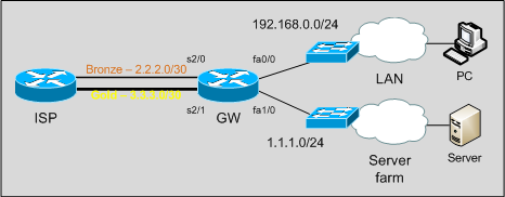
We have a router connected to the ISP with two WAN connections:

– a Bronze link, with little bandwidth, on which we have a /30 subnet;
– a Gold link, with good performances, on which we have a /30 point-to-point subnet and an additional /24 routed subnet.

DualWANScenario

Note that ISP does not accept inbound traffic coming from a subnet that is not the one routed through the ingress interface: for example, we can’t send traffic from 1.1.1.0/24 out the Bronze link. One subnet, one link.

Objectives

Our goals are:

– users on the LAN need access to Internet;
– mission critical traffic has to go out through the Gold link;
– our servers have to be reachable from the outside on their public IP addresses.

For the sake of simplicity, in our example and lab mission critical traffic will be telnet traffic. In real life it can be RTP, database or other important traffic.

At first sight, we can see there is no way to achieve Server farm fault tolerance: if the Gold link goes down, we can’t do anything to keep the subnet reachable. Ok, we can just tell the CIO to get a bigger budget for the network!

Solution

On this topology we have 5 interesting traffic flows:

LAN -> Mission critical services [Gold]
LAN -> WAN [Bronze]
LAN -> Server farm
ServerFarm -> WAN [Gold]
ServerFarm -> LAN

Traffic coming from the LAN towards WAN or Mission Critical Services needs to be translated by NAT too: remember that in the order of operations a packet is first routed, then translated, so actually we can focus just on routing packets out the box in the right way. We will take care about NAT later.

Standard routing just forwards packets on the basis of the destination network; it doesn’t care about Layer 4 properties nor source IP addresses. How can we route traffic on the basis of other elements, such as TCP destination port? If we want to route packets in the expected way we need to deploy Policy Based Routing(PBR). PBR, indeed, can take decisions on the basis of a lot of parameters: source address, destination ports, QoS marking.

Let’s proceed in an orderly fashion.

As first, this is the starting config:

interface Serial2/0
  description Bronze
  ip address 2.2.2.2 255.255.255.252
!
interface Serial2/1
  description Gold
  ip address 3.3.3.2 255.255.255.252
!
interface FastEthernet0/0
  description LAN
  ip address 192.168.0.1 255.255.255.0
!
interface FastEthernet1/0
  description ServerFarm
  ip address 1.1.1.1 255.255.255.0

We just have WAN interfaces up and running and the fastethernet interfaces pointing to the right subnet.

We set default route out to GW through the Bronze link:

ip route 0.0.0.0 0.0.0.0 Serial2/0

With this simple configuration we have already 3 of 5 flows routed in the right way:
– LAN to WAN
– LAN to ServerFarm
– ServerFarm to LAN

Now we need to start our PBR configuration! To do this, we need to create route-maps and then apply them to the ingress interfaces on which policy-based routed packets will enter.

As said, PBR can make decisions on the basis of a lot of elements, such as source address and Layer 4 properties. So, let’s define an access list to match Mission Critical Services (telnet in our example):

ip access-list extended GoldServices
  deny ip any 1.1.1.0 0.0.0.255
  permit tcp any any eq telnet
  deny   ip any any

The access-list just matches telnet traffic that is not directed to our Server farm.

Now we have to define a route-map matching Mission critical traffic and sending it out the Gold link…

route-map PBR_LAN permit 10
  match ip address GoldServices
  set interface Serial2/1 Serial2/0

… then we apply it to the LAN facing interface:

interface FastEthernet0/0
  description LAN
  ip policy route-map PBR_LAN

If a packet doesn’t match any route-map match statement it’s routed on the basis of the standard routing table (so, through the Bronze link).

Note that we used two interface names in the set interface command: if S2/1 is down, IOS will use S2/0, so we have a small level of redundancy and WAN side fault-tolerance for Mission Critical Traffic. We can achieve fault-tolerance for LAN to WAN traffic too by adding an higher metric default route:

ip route 0.0.0.0 0.0.0.0 Serial2/1 10

Now, LAN to Mission Critical Services is OK; we need to do the same for Server farm traffic:

ip access-list extended ServerFarm-To-WAN
  deny   ip 1.1.1.0 0.0.0.255 192.168.0.0 0.0.0.255
  permit ip any any
!
route-map PBR_ServerFarm permit 10
  match ip address ServerFarm-To-WAN
  set interface Serial2/1
!
interface FastEthernet1/0
  description ServerFarm
  ip policy route-map PBR_ServerFarm

Here our access-list does match traffic coming from the server farm to destinations outside the LAN: of course we don’t want to route ServerFarm-to-LAN traffic though the WAN! Unfortunately we can’t add a second interface to the set interface command: our ISP will not accept traffic coming from 1.1.1.0 on the bronze link.

Routing is OK, let’s take care about NAT.

We have 1 inside interface (the LAN facing fastethernet) and 2 outside interfaces:

interface FastEthernet0/0
  description LAN
  ip nat inside
!
interface Serial2/0
  description Bronze
  ip nat outside
!
interface Serial2/1
  description Gold
  ip nat outside

Here we don’t have to think about “policy-based NAT”: when NATting, policies have already been applied, and packets routed accordingly. We just have to translate them in the right way!

As first define the pool to use when translating Gold packets:

ip nat pool LAN-to-Gold 1.1.1.20 1.1.1.20 netmask 255.255.255.0

Then define 2 new route-maps, used in the ip nat inside source command:

route-map NAT_Gold permit 10
  match ip address LAN
  match interface Serial2/1
!
route-map NAT_Bronze permit 10
  match ip address LAN
  match interface Serial2/0

Finally:

ip nat inside source route-map NAT_Gold pool LAN-to-Gold overload
ip nat inside source route-map NAT_Bronze interface Serial2/0 overload

Both route-maps does match 192.168.0.0/24 traffic, but the first (NAT_Gold) takes care only of those packets routed through the s2/1 interface, while the second (NAT_Bronze) of packets routed through the Bronze interface. In this way we are sure the right inside global IP address will be used when translating.

Some tests… on the GNS3 Lab PC and Server are two routers:

traceroute and telnet from PC to “internet” (4.4.4.4 is a ISP loopback):

PC#traceroute 4.4.4.4 n
 Type escape sequence to abort.
 Tracing the route to 4.4.4.4
   1 192.168.0.1 68 msec 40 msec 16 msec
   2 2.2.2.1 120 msec *  52 msec
PC#
PC#telnet 4.4.4.4
 Trying 4.4.4.4 ... Open

 User Access Verification

 Password:

On the gateway, traceroute traffic is translated to 2.2.2.2 (Bronze link) while telnet to 1.1.1.20 (Gold link):

GW#show ip nat translations
Pro Inside global      Inside local       Outside local      Outside global
tcp 1.1.1.20:46878     192.168.0.10:46878 4.4.4.4:23         4.4.4.4:23
udp 2.2.2.2:49178      192.168.0.10:49178 4.4.4.4:33437      4.4.4.4:33437
udp 2.2.2.2:49179      192.168.0.10:49179 4.4.4.4:33438      4.4.4.4:33438
udp 2.2.2.2:49180      192.168.0.10:49180 4.4.4.4:33439      4.4.4.4:33439

A traceroute from the server, going through the Gold link:

Server#traceroute 4.4.4.4 n
Type escape sequence to abort.
Tracing the route to 4.4.4.4
  1 1.1.1.1 72 msec 52 msec 12 msec
  2 3.3.3.1 68 msec *  88 msec
Server#

You can download GNS3-Lab from GNS3-Labs.com: http://www.gns3-labs.com/2009/04/14/gns3-topology-dual-wan-connection-on-cisco-with-policy-based-routing-pbr/